Last Updated on June 6, 2023 by Eng Katepa
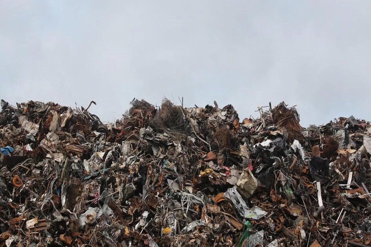
A landfill site, also known as a dump, rubbish dump, garbage dump, or dumping ground, is a site for the disposal of waste materials.
The safe and reliable long-term disposal of solid waste residuals is an important component of integrated solid waste management. Solid waste residues are waste components that are not recovered from conversion products or energy. Historically these wastes have been disposed of in the soil, on the earth’s surface, or deposited in the ocean.
It has been argued that many of the wastes placed in landfills or on land could be used as fertilizers to increase the productivity of the ocean or the land. Also, it has been argued that the placement of waste in ocean trenches where tectonic folding is occurring is an effective method of solid waste disposal. Nevertheless, landfill or land disposal is today the most common method used for solid waste disposal.
The term “sanitary landfill” was first used in the 1930s to refer to the compacting of solid waste materials. Initially adopted by New York City and Fresno, California, the sanitary landfill used heavy earth-moving equipment to compress waste materials and then cover them with soil. The practice of covering solid waste was evident in Greek civilization over 2,000 years ago, but the Greeks did it without compacting.
Today, the sanitary landfill is the major method of disposing of waste materials in North America and other developed countries, even though considerable efforts are being made to find alternative methods, such as recycling, incineration, and composting. Among the reasons that landfills remain a popular alternative are their simplicity and versatility.
For example, they are not sensitive to the shape, size, or weight of particular waste material. Since they are constructed of soil, they are rarely affected by the chemical composition of a particular waste component or by any collective incompatibility of co-mingled wastes. By comparison, composting and incineration require uniformity in the form and chemical properties of the waste for efficient operation. About 67% of the solid waste generated in the United States is still dumped in landfills.
This corresponds to several tons of waste per landfill daily, considering 4.5 lb (2 kg) of solid waste is generated each day per person in this country. Americans will have created approximately 220 million tons of solid waste in the year 2000. The many tons of solid waste dumped in a landfill today will not decompose until 30 years from now. In order to create environmentally friendly landfills, new sites are being engineered to recover the methane gas that is generated during decomposition, and some older landfills are being mined for useful products.
About 70% of materials that are routinely disposed of in landfills could be recycled instead. More than 30% of bulk municipal garbage collections consist of paper that could be remanufactured into other paper products.
Other materials like plastic, metal, and glass can also be reused in manufacturing, which can greatly reduce the number of waste materials disposed of in landfills, as well as preserve sources of nonrenewable raw materials.
The current design of municipal solid waste landfill liner systems utilizes granular and normally consolidated soil with geosynthetic materials to provide the required environmental and public health protection. Liner systems are required to isolate the waste from the natural subsoil and groundwater.
The effect of land subsidence caused by sinkholes is an important design factor for municipal solid waste landfill liner systems. A high potential for sinkhole effects is evident in the central Florida area due to the geological conditions.
Sinkhole occurrence under the landfill can cause the ultimate failure of the liner system, thus allowing contamination of the natural subsoil and groundwater. The liner system becomes the sole base to bridge the cavity and withstand the overburden pressure. Failure of the liner system becomes a function of the geosynthetic yield strength and its maximum allowable deformation.
In this study, the design of a landfill liner system for implementation above sinkholes is based on soil arching the tension member theories. It is assumed that the natural subsurface soil deforms across a developing void thereby forming an arch. The design procedure accounts for the cumulative effects of soil types as single or multiple layers with geosynthetic materials.
A series of charts are developed for various sizes of sinkhole cavity versus strength parameters of typical soils used in landfill liner systems design.
Also Read: Best Engineering Books For Engineers
1.1.1. Landfill – Sanitary Landfill
Sanitary landfills involve well-designed engineering methods to protect the environment from contamination by solid or liquid wastes. A necessary condition in designing a sanitary landfill is the availability of vacant land that is accessible to the community being served and has the capacity to handle several years of waste material. In addition, cover soil must be available.
Historically, landfilling has been the environmentally and most economical acceptable method for the disposal of solid waste all over the world. Even with the implementation of waste reduction, recycling and transformation technologies, disposal of residual solid waste in landfills still remain an important component of an integrated solid waste management strategy.
1.2.0 Landfill – Method types.
Designs may vary, but there are three basic methods of building a sanitary landfill: area method, trench method, and ramp method.
1.2.1 Landfill Area method
The area method is best suited for sites where no natural slopes exist. This method can be adapted, however, to ravines, valleys, quarries, or old surface mines. Disposing of waste in a ravine site requires the construction of diversion ditches for runoff water before any waste is received.
Here is how the area method works: Waste is pushed into layers, compacted, and adequately covered. During succeeding days, the incoming waste is dumped at the toe of the preceding day’s waste and pushed up the face, compacted, and covered at the end of each working day. A machine, such as a track-type tractor or landfill compactor, spreads and compacts the material. Soil for daily cover must be hauled in from borrow sites using a wheel tractor-scraper or articulated truck.
1.2.2 Landfill Trench Method
The trench method is best suited for flat or gently sloping land where the groundwater table is deep below the surface. The chosen site should have soil that is easy to excavate and suitable for cover. Immediate availability of cover without the need for expensive specialized equipment to haul it long distances can be a major advantage of the trench method. If the landfill is to be brought above ground level, nearby cover material can also be an advantage.
The trench does, however, have some disadvantages. If more cover material is excavated than can be used immediately, it will have to be stockpiled and moved again at an additional expense. Drainage, too, can be a problem, but it can be solved by “daylighting” one end of the trench and sloping the trench floor toward that end.
Provisions must also be made to allow surface water to run off at the end of the trench. Small trenches usually measure eight to 10 ft deep and are two to three times as wide as the machine excavating them. Larger ones maybe 30 to 40 ft deep, 60 to 80 ft wide, and 200 to 300 ft long. These are suitable for sites receiving 300 to 500 TPD. Note that 500 tons are usually the limit to avoid truck traffic congestion.
There are three ways to trench:
Excavate the entire trench, and windrow the cover material along the sides until it is needed.
Excavate only far enough to provide a single day’s working space and dirt cover. This is called the progressive trench method, and it may require handling the cover material only once.
Excavate a second trench in segments parallel to the first one, and use the excavated material as cover for the first trench. Take care to leave at least two ft between the two trenches. This method may allow for handling the cover material only once.
Also Read Engineer | Definition, and History You Should Know Right Now
1.2.3 Landfill Ramp Method.
The ramp method is a variation of the area and trenching techniques. Waste is spread and compacted on an existing slope. Cover material is excavated directly in front of the waste. It is then spread over the waste and compacted. The excavated area becomes a part of the cell to be worked on the following day.
Similar to the progressive trench method, the ramp method is considered ideal by some operators because they do not have to haul in cover material (with its extra cost of expensive handling equipment). Because they may handle the cover only once and do not have to prepare the land in advance, they consider this an excellent way to start a landfill with a minimum of equipment.
If more than one lift is required, the cover will have to be hauled to the working face at an additional expense. The depth of the water table is another factor, but it is not as critical as the trench method, which normally requires deeper excavation.
1.2.4 . Other Modified Methods
Several modifications of basic landfill techniques are being used to extend site life decrease the need for cover material, and save costs.
The high-rise method involves stacking and compacting layers of waste on the ground surface, then covering each layer. Layers are placed on top of the other like a pyramid. However, as the layers move upward, the slopes reduce the size of the top area.
Stacking the layers above ground minimizes subsurface pollution and makes maximum use of the limited land area. This method is popular in coastal areas or where the water table is high. You may need to haul cover material from other locations.
The no-cover method involves spreading and compacting waste without covering it at the end of the day. This method, however, requires certain standards regarding insect control, rats, odors, and other nuisances. Although it can extend the life of a landfill by 10 to 20 percent and cut operating and equipment costs, the no-cover technique has not been accepted in most locations.
Trench and area methods, along with combinations of both, are used in the operation of landfills. Both methods operate on the principle of a “cell,” which in landfills comprises the compacted waste and soil covering each day. The trench method is good in areas where there is relatively little waste, low groundwater, and the soil is over 6 ft (1.8 m) deep.
1.3.0 Special Use Areas.
The design of a landfill should also include provisions for special circumstances. For instance: An area near the landfill entrance where collection trucks can deposit their loads when wet weather prevents them from reaching the working face. An area for demolition debris that normally does not have to be covered every day the way routine wastes do.
Special areas or areas where toxic waste cleared for landfill disposal can be deposited. Areas for disposal of bulky wastes such as tree stumps. Storage area for appliances and junk cars, if they are received in sufficient quantity to make this provision economical and are permitted for storage. Areas for yard waste, including grass clippings, brush, mulch, and small branches when the site is permitted for this material. Citizen bin for the safety of small private vehicles. An area for a tub grinder to process landscape and wood waste.
1.4.0 Compaction
1.4.1 Better Compaction = Long Landfill Life
Selecting a new disposal site and getting approval can be challenging. Governmental officials lend a willing ear to any practical proposals that will help them extend the life of their present sites. Compaction is the best answer. Better compaction means packing more waste into less space. Here are several benefits:
- Extends the life of the site
- Decreases settlement
- Reduces voids
- Reduces wind-blown litter
- Discourages insects and rodents
- Reduces the possibility of waste washing away or being exposed during a rain
- Reduces the amount of daily cover needed, thereby reducing machine excavation work
- Reduces leachate and methane migration
- Provides a more solid travel surface for refuse trucks, reducing maintenance and repairs
Loose residential and commercial wastes weigh about 400 to 500 lb/cu yd. A refuse collection truck will increase that density to 800 to 1,000 lb/cu yd. At the landfill, in-place refuse density can vary from 600 to 1,500 lb.
Moderate compaction should provide densities of 800 to 1,000 lb. But by dumping and pushing the waste into the fill, densities are considerably less…as low as 600 lb/cu yd.
The greatest compaction is achieved in landfills that accept a high proportion of demolition debris such as brick, stone, and concrete. Densities of as much as 2,500 lb/cu yd can be achieved. It is common for construction and demolition materials to have specific landfills. The cover material will add another 100 to 200 lb/cu yd to landfill compaction density.
Also Read Types of Glasses for Construction You Need To Know In 2023
1.4.2 Compaction Factors
1.4.2.1 Compaction Density
The bulk density of the refuse; in this parameter seems to be about 300kg/m3 in some municipalities in Tanzania except in Dar es salaam where the value was as high as 550kg/m3 probably due to the high proportion of the fine dust.
Compaction ratios achieved with wastes from industrialized countries (with initial densities in the range of 130 to 190 kg/m3) vary from 2:1 to 4:1, the final density in the vehicle being about 400 to 550 kg/m3. Wastes in most developing countries have an initial density similar to that of compacted industrialized wastes.
1.4.2.2 Refuse Layer Thickness.
The thickness of the layer is the most important factor. To obtain the greatest density, waste should be spread in layers not more than two ft deep and compacted. The thicker the layer, the less densely a machine can compact it.
1.4.2.3 The Number Passes
A compaction machine-made over the refuse is another factor that affects density. A pass is defined as a machine traveling over refuse one time in one direction. Whatever the machine, it should take three to four machine passes to achieve the best results. More than four passes do not achieve enough additional density to make them economical.
1.4.2.4 Slopes
The slope should be kept to a minimum of 4:1 or less. A level surface allows the best compaction. However, working refuse up a slope does have advantages:
- The working slope covers less area than a flat working face, reducing litter problems and the amount of cover material needed.
- When a machine works uphill, rather than downhill, it is easier to achieve a more uniform lift thickness over the entire area since refuse material will not roll ahead of the blade and pile up at the toe of the slope. Having noted these situations, it must be emphasized that in almost all cases, flatter is better for maximum compaction.
1.4.2.5 Moisture Content.
Compaction density is considerably affected by moisture content. Water softens and acts as a lubricant for materials such as paper and cardboard, and permits tighter consolidation. Field tests show that moisture content varies from 10 to 80 percent, depending on whether the season is wet or dry. The optimum moisture content for maximum compaction is about 50 percent.
A minimum amount of moisture can increase refuse compaction density by ten percent. While higher moisture content can provide higher in-place densities, it also increases the amount of leachate formation.
2.4.2.6 Other Factors.
Several factors affect the operation of a landfill. As a result, they must be carefully considered in planning an efficient disposal system.
Wet weather.
This is a major factor to consider. Although main access roads may be all-weather construction, you should prevent roads leading to the working face or the cover borrow site from becoming quagmires. This can be accomplished by spreading gravel, cinders, crushed rock, or small-size demolition rubble on the haul roads. In wet weather, it is wise to restrict landfill equipment from operating on the roads.
Tires.
Disposing of tires can be a headache. In fact, most landfill sites are prohibited from accepting them. Tires are resilient and almost impossible to compact. As a result, they literally push themselves up through the waste cell. To help eliminate such a problem: Consider alternative tire disposal methods, such as shredding and recycling.
Spread tires out in single layers at the toe or bottom of the fill. If they come into the fill at the end of the day, store them until the next day. Spread the incoming brush over the tires. It acts like a woven mat to keep them flat. If the brush is not available, cover tires with construction or demolition waste such as boards, plywood, or sheetrock.
Wire.
Wire is another difficult material to handle. The wire from bedsprings, fences, and cables can wrap around the wheel axles and undercarriages of landfill machines and cause damage. Such material should be pushed to the toe of the fill, taking care that it does not roll or slide under the dozer blade. Then brush or demolition debris should be placed over it to keep it from working up and entangling itself in machines.
Settling.
The rate and extent of the settlement will depend on the type of waste, the depth of the fill, how fast the waste decomposes compaction density, and the ratio of cover material to waste. Most settling occurs during the first three to five years after the refuse has been buried. Even after a landfill is closed out, cracks and depressions should be filled and drainage problems corrected until the land has completely stabilized.
Litter.
Windblown litter is a persistent operating nuisance, and controlling it should be a major concern. There are several ways to handle the problem: Keep the size of the working face as small as possible. Cover cell portions as they are constructed. Install litter fences near the unloading and spreading area. Pick up litter frequently.
Letting it accumulate along fences renders them ineffective. Post and enforce regulations to restrict hauling uncovered loads into the landfill. Unload wastes at the bottom of a sloped work face. Wind cannot pick them up as readily there. When building a trench-type disposal site, build trenches at right angles to prevailing winds.

1.5.0 Gas and Leachate.
The greatest threats may be the unseen ones: gas and leachate. Gas is generated by waste decomposition. Leachate forms as surface or groundwater seep through wastes, picking up chemicals and biological contaminants.
Landfill gas such as methane can seep into nearby buildings and cause fires and asphyxiation. Leachate can find its way into walls, streams, and lakes, poisoning drinking water and killing fish. Both gas and leachate can be controlled with proper landfill engineering and operating techniques.
Gas generation can also be a plus because it can be sold for additional revenue. Several types of passive and active gas-venting systems can be installed at a landfill. Their objective is to keep possibly dangerous levels of methane from diffusing underground. Passive systems let the gas vent itself out of the landfill and active systems pump the gas out.
Passive systems need little attention. Active systems require periodic maintenance. Sinking monitoring wells to check gas generation helps determine the system’s effectiveness. The liquid that intrudes into the landfill to create leachate comes from four sources: groundwater, liquids placed in the landfill, rain or snow falling in the fill, and surface runoff flowing in.
The site operator can limit leachate with proper design and operation. The generation of leachate can be reduced by compacting waste properly, spreading and compacting cover to the right depth, and building and maintaining proper surface drains around the site.
Leachate can be controlled by placing liners at the landfill base and installing systems to collect the contaminant before it seeps out of the landfill. The liners’ purpose is twofold, as they also keep groundwater
from entering the site. Some sites depend on natural dissipation to control the movement of leachate. Installing control devices will be an ongoing process during the site’s operation. Careful installation and proper maintenance are essential. Install leachate controls as new areas open, or as old areas are finished.
Monitor wells frequently to determine whether unacceptable leachate amounts are escaping from the landfill. Consult government regulations to make certain your program is in compliance.
1.5.1 Leachate Generation.
The volume of the leachate in the sanitary landfill depends on the following factors:
- Rainfall in the landfill area.
- Surface runoff and/ or groundwater filtration.
- Evapotranspiration.
- The natural moisture of the MSW
- Degree of compaction.
- Field capacity (Capacity of the soil and the MSW to retain moisture)
The volume of the leachate depends basically on the rainfall. Leachate is produced not only by runoff but also by rainfall in the area of the landfill, which increases the quantity, either by direct precipitation on the waste deposited there or by increasing the amount of filtration through cracks in the terrain.
Owing to the different conditions of operation and location of each landfill, the expected rates can vary, so they will need to be calculated for each individual case. Since it is difficult to obtain local climatologic information, the volume of leachate produced is often determined by using coefficients that correlate with the previously mentioned factors.
The Swiss method can be used to make a simple and quick estimate of the flow of the leachate or percolated liquid by using the equation;
Q = 1/t * P * A * K
Where; Q = Mean flow of leachate,e. (l/s).
P = Mean annual precipitation (mm/year)
A = Surface area of the landfill (m2 )
t = Number of seconds in a year (31,536,000 s/year).
K = Coefficient that depends on the degree of compaction of the waste.
The recommended values of which are the following.
For weakly compacted landfills with a specific gravity of 0.4 to 0.7 t/m3, the estimated production of leachate is between 25 and 50% (K = 0.25 to 0.50) of the mean annual precipitation of the landfill area.
For strongly compacted landfills with a specific gravity > 0.7 t/m3, the estimated production of leachate is between 15 and 25% (K = 0.15 to 0.25) of the mean annual precipitation for the landfill area. Observations made at several small landfills have confirmed that leachate generation occurs chiefly during rainy periods and for several days afterward, and stops during dry periods.
It would therefore be a good idea to use an adaptation of the above method to calculate the leachate generation from precipitation during the rainy months and not during the whole year. This criterion is important when estimating the leachate drainage or storage system for manual sanitary landfills.
Therefore, it is suggested that the precipitation records used to be those of the month of maximum rainfall, expressed in mm/month. This method will give a good approximation of flow:
Qlm = Pm * A * K
Where Qlm = Mean leachate flow generated (m3/month).
P = Maximum monthly precipitation
A = Surface area of the landfill (m2.)
K = Coefficient that depends on the degree of waste compaction
1m = 103 mm.
1.6.0 Cover.
The right cover material and proper handling techniques help control as well as health and environmental problems. Cover material: Must be compacted to provide a tight seal. Must be free of organic material and large objects. Must not crack excessively when dry.
Cover material is valuable and provides the following benefits:
Helps seal in odors and prevents water from entering compacted waste. Prevents the breeding of insects and eliminates a source of food and shelter for rodents and birds. Prevents fires and controls litter.
Provides a dense, stable fill that can serve as a good road base. A few landfills have been allowed to permit limited rainwater entry to facilitate waste decomposition.
Also Read: Engineering Ethics
1.7.0 Weighing.
Keeping accurate statistics on incoming waste amounts is the only way to get reliable information to determine current and future landfill needs. Weighing the waste as it comes into the landfill is the best way to gather this data. Such weighing provides the most equitable basis for establishing tipping fees. It also provides the necessary input for the cost analysis of the operation.
Weighing also gives the operator a way to check the volume of waste cells and the amount of coverage that is used. Scale facilities are an important part of landfill facilities. However, because a scale facility for a small landfill is sometimes hard to justify, finding another method for gathering information about the amount of incoming waste is essential.
A periodic vehicle count is one way a landfill can collect this data. Relating this to the tonnage or cubic yard capacity of each truck gives a reasonable estimate of the tonnage (yardage) coming in each day. Remember that such a count should be made on representative days of the week and carried on throughout the year to figure in seasonal variations.
1.8.0 Fires.
Because most landfill fires start from outside sources rather than spontaneous combustion, an operational firefighting plan is necessary. Here are some suggestions:
- Prohibit smoking on or near the working face. Post signs and enforce the rule.
- Supply all landfill equipment with extinguishers sufficient enough to put out small fires.
- Use the water wagon’s high-pressure stream to put out fires.
- Put down bigger fires by spreading them out with a dozer, for example, and covering them with dirt.
- Divert drivers bring in smoking or burning loads to a safe area away from the working face.
- Remember that daily earth cover can keep the fire within the sell; preventing it from spreading if spreading throughout the landfill.
1.9.0 Landfill – Decomposition.
A landfill has three stages of decomposition. The first one is the aerobic phase. The solid wastes that are biodegradable react with the oxygen in the landfill and begin to form carbon dioxide and water. The temperature during this stage of decomposition in the landfill rises about 30°F (16.7°C) higher than the surrounding air.
1.10.0 Landfill – Operating Principles
While landfills may outwardly appear simple, they need to operate carefully and follow specific guidelines that include where to start filling, wind direction, the type of equipment used, method of filling, roadways to and within the landfill, the angle of slope of each daily cell, controlling contact of the waste with groundwater, and the handling of equipment at the landfill site.
1.11.0 Landfill – Alternatives To Landfill
The United States Environmental Protection Agency (EPA) requires all new landfills to include a leachate collection system. Recirculation of leachate accelerates the decomposition of solid waste. Another alternative use of landfills is to capture the methane gas produced during decomposition to generate electricity.
1.12.0 Landfill – Recycling
As a method of reducing the costs of solid waste disposal in landfills and solving the problem of finding suitable landfill sites, many communities have initiated recycling programs. Some programs are carried out by segregating and collecting the recyclables separately from the materials destined for the landfill. There are also many drop-off programs for specific items such as bottles, plastic, and metal waste.
Landfill – Composting
The composting of organic materials for reuse in gardening and in agriculture can help alleviate the problem of using land to dispose of waste material. Plant and food substances are biodegradable, which means they are capable of decomposing through the agency of bacteria, fungi, and other living organisms. Temperature and sunlight play a role in the decomposition of biodegradable substances.
1.13.0 The Science Of Sanitary Landfill:
Interwaste has established itself as a Southern African Leader in the technologically demanding area of Landfill construction and development. The professional knowledge and expertise accumulated over many years in this field allow the company the opportunity of involvement in ensuring that, the highest standard and the best practice are utilized at every stage of every project.
Modern solid waste landfill facilities are falling under increased regulatory scrutiny to ensure that they are more protective of the environment than has been the case in the past. Open dump methods are no longer considered.
Acceptable and sophisticated technology is now utilized to ensure that, the sanitary landfill, operates, often for decades as the safe and efficient final destination for the bulk of society’s waste.
Technical specification details and best practice parameters covering every aspect of landfill design and construction are laid down in the minimum requirement document of enviromentation published by the government through the Environment Affairs and Tourism (D.E.A.T.), and the Department of Waste Affairs and Forestry (D.W.A.F) who shoulder the ultimate responsibility for the protection of the South African environment.
In order to appreciate the important part played by Interwaste within the landfill management industry, it may be useful to understand the basic principles that govern sanitary landfill design and construction and the way in which the landfill is classified.
The concept of a Sanitary Landfill was developed in order to minimize any adverse environmental impact and operates in accordance with the basic principles namely Compaction and Cover.
1.13.1 Compaction
Compaction of waste is normally affected by heavy equipment passing over the waste that has been deposited in thin layers. This optimizes air-space usage and reduces the amount of cover material required, effectively extending the operational lifespan of the site.
Void reduction within the waste also reduces the movement of leachate, reduces the risk of fire, and discourages vermin. The purpose of compaction is to reduce the air void to the solid waste and the covering material so as to reduce the penetration of leachate, reduce the effect of fire, and discourages vermin.
Because of the effect of settlement, an increase in density becomes a continuing phenomenon. The in-place density of a properly operated, relatively deep fill can be on the order of 900 kg/m3; whereas that of a poorly compacted fill would be only about 300 kg/m3. In the United States, the usual range of density directly after compaction is on the order of 475 to 712 kg/m3
1.13.2 Covering
The compulsory Covering of compacted waste on a daily (or more frequent) basis is primarily aimed at eliminating odors but also succeeds in reducing litter and fire risk discourages and generally improves the aesthetics of the site.
Generally, a daily cover of a minimum of 150mm of compacted soil or other suitable material (for example building rubble) is required to effectively isolate each day’s waste from the environment. When considering the siting and design of a proposed sanitary landfill site, provision must be made for sufficient cover material to last throughout the projected lifespan of the facility.
1.13.3 Classification
All landfill sites are classified according to three basic criteria namely
- Waste type.
- Landfill size.
- Site water balance or Leachate potential.
1.13.3.1 Waste Type.
The waste type that may be disposed of at any given site is divided into two basic types being
1. General (G) waste.
2. Hazardous (H) waste.
Hazardous wastes are further divided (H or h) depending on a hazardous material rating scale.
1.13.3.2 Landfill Size.
Landfill size is determined by the calculated volume of waste that any site can receive per day. Rating range from C (communal landfill, up to 50 tons per day), to S (Small landfill, up to 200 tons per day), M (Medium landfill, up to 500 tons per day), and L (Large landfill, over 500 ton per day)
1.13.3.3 Equipment Required At Landfill Site.
(Table 1)The type of equipment required at the site depends on the daily capacity of the landfill
| Daily Capacity (t) | Number | Type | Size (t) | Accessory |
| 0 – 50 | 1 | Tractor crawler or rubber – tyred | 5 – 15 | Dozer blade landfill blade Front–end loader (1 – 2 m) |
| 50- 150 | 1 | Tractor crawler or rubber tyred scraper dragline water truck | 15 – 30 | Dozer blade landfill blade Front–end loader (2 – 4 m) Multipurpose bucket |
| 150- 300 | 1 – 2 | Tractor crawler or rubber tyred scraper dragline water truck | 15 or more | Dozer blade landfill blade Front–end loader (2 – 5 m) Multipurpose bucket |
| 300 or more | 2or more | Tractor crawler or rubber–tyred scraper dragline steel wheel compactor Road grader water track | 22 or more | Dozer blade landfill blade Front–end loader Multipurpose |
1.13.3.4 Leachate Potential
General waste landfills are classified in terms of their leachate potential. Any landfill (designated.–site) has the potential to generate sporadic leachate in excessively wet weather conditions. However, only those sites that have the potential to generate significant leachate which could impact adversely the environment (designated + sites) are required to utilize a leachate management system.
1.14.0 Landfill Development:
The development stages of a typical landfill are summarized as follows
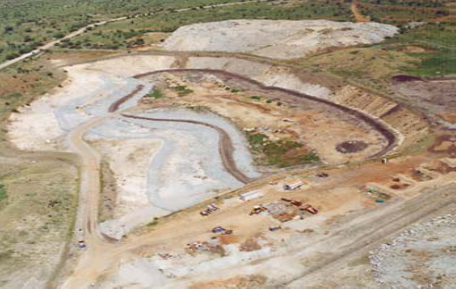
1.14.1 Landfill Site Selection.
Good landfill site selection provides for simple cost-effective design, which provided the site presentation is correctly carried out providing for a good landfill operation. This in turn ensures the environmental acceptability of the landfill.
1.14.2 Landfill Permitting
Once a landfill site has been identified and the study has confirmed its feasibility, the application must be made for a permit for that site to be developed. This procedure includes the generation of an Environment Impact Assessment. (EIA) which must be approved by (DEAT)
1.14.3 Landfill Design
The general objective of the current landfill design is to provide a cost-effective, environmentally acceptable waste disposal facility. The design must mitigate any adverse impacts that may have been identified and prevent leachate prolusions of adjacent ground and surface water.
It must also provide for sufficient cover material to ensure an environmentally and aesthetically acceptable operation. As modern sanitary landfill practice dictates that a layer of covering material must be placed on top of compacted waste at the end of each working day, the eventual total capacity of the site is dictated by the volume of cover material available.
The following illustration shows the variation of complexity in landfill linear design depending on the classification of the site, starting with the simplest communal general waste (G: C: B) facility.
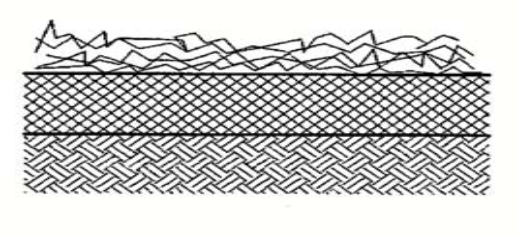
- Waste body
- 150mm base preparation layer.
- In-situ soil
At the totally opposite end of the scale would be an H: H. Classification site, designed to handle the highest level of hazardous wastes. Its’ construction diagram illustrates the highly demanding design criteria required for a site of this nature.
Between these two extreme cases are eight further classifications with together accommodate the total scope of landfill requirements.
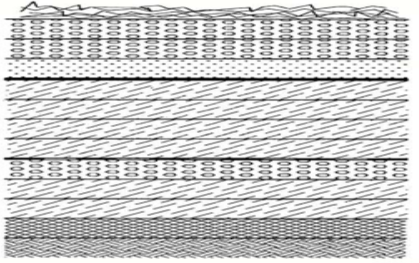
- Waste body.
- 300mm leachate collection layer.
- 150mm soil protection layer.
- 2mm FML Geomembrane.
- 600mm compacted clay liner (in 4*150mm layers)
- Geotextile layer over 150mm leakage detection / collection layer.
- 300mm compacted clay liner (in 2*150mm layer).
- 150mm base preparation layer.
- In-situ soil.
1.15.0 Basic Landfill Design Concept
Storage of any waste material in a landfill poses several potential problems. One problem is the possible contamination of soil, groundwater, and surface water that may occur as leachate produced by water or liquid wastes moving into, through, and out of the landfill migrates into adjacent areas.
With the possibility of hazardous wastes, landfills should be designed to prevent any waste or leachate from ever moving into adjacent areas. The HELP model has been developed specifically as a tool to be used by designers and regulatory reviewers for selecting practical designs that minimize potential problems.
Leachate is described as a liquid that has percolated through layers of waste material. Thus, leachate may be composed of liquids that originate from a number of sources, including precipitation, groundwater, consolidation, initial moisture storage, and reactions associated with the decomposition of waste materials.
The chemical quality of leachate varies as a function of a number of factors, including the quantity produced, the original nature of the buried waste materials, and the various chemical and biochemical reactions that may occur as the waste materials decompose.
In absence of evidence to the contrary, most regulatory agencies prefer to assume that any leachate produced will contaminate either ground or surface waters; in light of the potential water quality impact of leachate contamination, this assumption appears reasonable.
1.15.1 Leachate Control
The quantity of leachate produced is affected to some extent by decomposition reactions and initial moisture content; however, it is largely governed by the amount of external water entering the landfill. Thus, a key first step in controlling leachate migration is to limit production by preventing, to the extent feasible, the entry of external water into the waste layers.
A second step is to collect any leachate that is produced for subsequent treatment and disposal. Techniques are currently available to limit the amount of leachate that migrates into adjoining areas to a virtually immeasurable volume, as long as the integrity of the landfill structure and leachate control system is maintained.
Drainage layers, geomembrane liners, and barrier soil liners may be referred to as the leachate collection and removal system or a double liner system. After the landfill is closed, the leachate collection and removal system serves basically in a backup capacity. However, while the landfill is open and waste is being added, these components constitute the principal defense against contamination of adjacent areas.
The combination of site selection, surface grading, transpiration from vegetation, soil evaporation, the drainage through the sand, and the low hydraulic conductivity of the barrier soil and geomembrane liners serve effectively to minimize leachate production from external water. The cap should be no more permeable than the leachate collection and removal system so that the landfill will not gradually fill and overflow into adjacent areas following the abandonment of the landfill.
Modern sanitary landfills differ significantly from the open dumps of old. They even differ from the landfills of only a few years ago. Sanitary landfills use technology to contain waste and prevent the leaching out of potentially hazardous substances. These substances can be carried in the rainwater that passes through the trash contained in an improperly-designed landfill. The resulting liquid runoff is called leachate.
To prevent groundwater contamination, layers of compacted clay and thick plastic cover the bottom of the landfill. Running horizontally between and above the liners, a system of perforated pipes collects the leachate that has percolated through the trash. These pipes channel the leachate to a treatment center where toxins are removed. Numerous wells surround the landfill site, providing a means to monitor the quality of nearby groundwater.
1.15.2 Definition of Terms Used in Landfill Design
A landfill – is a physical facility used for the disposal of solid waste materials.
A secured landfill – is the physical facility used for the disposal of hazardous solid waste matters. This is always done under special care depending on the type of hazardous mater obtained.
Landfilling – is the process by which solid waste materials are placed in a landfill.
Cell – is the term used to describe the volume/thickness of the solid waste materials placed in the landfill, always given in layers which include solid waste and soil cover per day.
Leachate – is the liquid collected at the bottom of the landfill.
Landfill gases – these are the mixture of gases found within the landfill due to different materials placed and the variation of the temperature in it.
Landfill liners – these are materials, both natural and artificial/manufactured that are used to line the bottom area below the grade sides of the landfill.
A Sanitary landfill – is the engineering facility for disposing of M.S.W.W. designed and operated to minimize the public health and environmental impact. Designed to save more than 500 people at once.
1.15.3 Sources Of Solid Waste That Are Possibly Disposed Of The Landfill
The solid wastes to be disposed of in the landfill are obtained from different sources including the following.
Garbage – This refers to the putrescible solid waste constituents produced during the preparation or the storage of fruit, meat, vegetables, and so on. These wastes have a moisture content of about 70%.
Rubbish – This refers to the putrescible solid waste constituents either combustible or non-combustible.
Combustible waste includes paper, wood, scrap, rubber, leather, and so on.
Non-combustible wastes are metal, glass, ceramic, and so on. These contain moisture contents of about 25%
Pathogenic waste – These refer to dead animals, and human wastes, they contain moisture of about 85%
Industrial wastes – These include chemicals, paints, sand, metal ores processing, fly ash, sewage treatment sludge, and so on.
Agricultural waste –These include the farm animal manual, crop residues, and so on.
Generally, the principal sources of solid waste are domestic activities, commercial activities, industrial activities, and agricultural activities. In this case, commercial and domestic solid wastes are considered together as urban waste.
This is because; the main constituents of urban solid wastes are similar all over the world. But; the weight generated, the density, and the proportion of the constituent vary widely from country to country, and from town to town within a country according to the level of economical development, geographical location, weather, and social conditions.
All in all; it has been found that, as personal income rises, then the kitchen wastes decline/decreases. While paper, metal, and glass waste increases. Therefore; the total weight generated rises/increase but the density of the waste decrease.
1.16.0 Help Model Description.
The HELP model requires daily climatologic data, soil characteristics, and design specifications to perform the analysis. Daily data may be input by the user, generated stochastically, or taken from the model’s historical database.
1.16.1 Synthetic Weather Generation
The HELP user has the option of generating synthetic daily precipitation data rather than using default or user-specified historical data. Similarly, the HELP user has the option of generating synthetic daily mean temperature and solar radiation data rather than using user-specified historical data.
The generating routine is designed to preserve the dependence on time, the correlation between variables, and the seasonal characteristics in actual weather data at the specified location. Coefficients for weather generation are available for up to 183 cities in the United States.
1.16.2 Moisture Retention And Hydraulic Conductivity Parameters
The HELP program requires values for the total porosity, field capacity, wilting point, and saturated hydraulic conductivity of each layer that is not a liner. Saturated hydraulic conductivity is required for all liners.
Values for these parameters can be specified by the user or selected from a list of default values provided in the program. The values are used to compute moisture storage, unsaturated vertical drainage, head-on liners, and soil water evaporation.
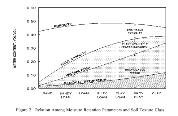
1.16.3 Moisture Retention Parameters.
The soil water content or storage used in the HELP model is on a per-volume basis (q), the volume of water per total volume. Engineers commonly express moisture content on a per-mass basis. The two can be related to each other by knowing the dry bulk specific gravity (Gdb) of the soil (ratio of dry bulk density to water density), (q = w × Gdb), or wet bulk specific gravity, Gwb (ratio of wet bulk density to water density), [q = w × Gwb / (1+ w)].
Total porosity is an effective value, defined as the volumetric water content when the pores contributing to change in moisture storage are at saturation.
Field capacity is the volumetric water content at a soil water suction of 0.33 bars or remaining after a prolonged period of gravity drainage without additional water supply.
Wilting point is the volumetric water content at the suction of 15 bars or the lowest volumetric water content that can be achieved by plant transpiration. These moisture retention parameters are used to define moisture storage and relative unsaturated hydraulic conductivity.
The HELP program requires that the wilting point be greater than zero but less than the field capacity. The field capacity must be greater than the wilting point and less than the porosity. Total porosity must be greater than the field capacity but less than 1 (one).
The general relation between moisture parameters and soil texture class is shown below.
The HELP user can specify the initial volumetric water contents of all non-linear layers. Soil liners are assumed to remain saturated at all times. If initial water contents are not specified, the program assumes values near the steady-state values (allowing no long-term change in moisture storage) and runs a year of simulation to initialize the moisture contents closer to the steady-state.
1.16.4 Hydraulic Conductivity
The HELP program uses the saturated and unsaturated hydraulic conductivities of soil and waste layers to compute vertical drainage, lateral drainage, and soil liner percolation. The vapor diffusivity for geomembranes is specified as a saturated hydraulic conductivity to compute leakage through geomembranes by vapor diffusion.
Saturated hydraulic conductivity is used to describe flow through porous media where the void spaces are filled with a wetting fluid (e.g. water). The saturated hydraulic conductivity of each layer is specified in the input.
Unsaturated hydraulic conductivity is used to describe flow through a layer when the void spaces are filled with both wetting and non-wetting fluid (e.g. water and air
1.16.5 Design Specifications
- Slope and maximum drainage distance for lateral drainage layers
- Layer thickness
- Leachate recirculation procedure
- Surface cover characteristics
- Information about geomembrane
We hope this article helped you learn about Landfill: General Overview. You may also want to learn about What is the Function of Buildings? , The Best Garden Hoses of 2022, Best Types of Kitchen | All You Need To Know- Right Now, and Problem-Solving | All Skills You Need To Know
If you liked this article, please Join WebsiteForEngineers on Telegram, and you can also find us on Pinterest, Twitter, and Facebook.