Last Updated on March 10, 2023 by Eng Katepa
Water supply design involves providing convenient and sufficient access to safe and potable /palatable water in a given design area and given design period of time. Also have to fulfill these requirements at a minimum cost for the construction, operation, and maintenance of the project.
1.1 Water supply design includes;
- Determination of water demand
- Identifying of water source and its capacity
- Designing of gravity main whereby diameter, velocity, and material of the pipe will be determined
- Determination of water storage tank capacity
- Designing of a distribution network whereby diameter, materials type, discharge, and velocity will be determined
1.2 Water sources
After estimating water requirements for the water supply scheme, the second thing is searching for nearby water sources which may be able to supply the required amounts of water. The various sources of water available on the earth can be classified into two categories:
Surface sources such as;
- Ponds, lakes, streams, and rivers
- Storage reservoirs.
Underground sources;
- Springs
- Boreholes
Water source selection
The process of choosing the water source for the water supply scheme depends on;
- Source availability
- water quality
- Economic feasibility
1.3 Surface Water Intakes
Surface water intake is the first point where the water is off-taken from the source. The source can be a pond, lake, river, stream, or canal. The basic function of the intake structure is to help in the safe withdrawal of water from the source than to discharge water into the withdrawal conduit through which it flows up to the water treatment plant.
1.3.1 River/ stream intakes
Water from the river is always drawn from the upstream side because it is free from contamination caused by the disposal of sewage in it. Also located in a place that will not erode easily. The intake should be deep enough to avoid being above the minimum recorded river level, while not too low to capture the bottom sediments.
1.3.2 Special intakes
There are two types of special intakes:
a) Simple strainer and tripod intake– This type of intake is installed in the small stream where the discharge is almost the same.
b) Weir intake– This type is used where the stream water level is low and has to be raised in order to form an intake then a weir would be ideal.
1.3.3 Location of intake site
Points to consider:
a) The intake should be located at a point where the best quality of water will be withdrawn from the source.
b) The site selected permits greater withdrawal of water even during the driest period of the year.
c) The site remains easily accessible during floods and should not get polluted.
d) Never located downstream or in the vicinity of the point of disposal of wastewater.
e) Sediment transport, erosion of the river banks, and silt concern.

1.4 Gravity Main
The pipelines are laid/installed, in order to convey water from a high leveled source to the treatment plant or storage tank at lower levels by mere action of gravity without any pumping. For proper functioning of the system, the difference of head available between the source and other localities must be sufficient enough, as to maintain adequate pressure at the consumer’s doorsteps, after allowing the frictional and other losses in the pipes. This method is the most economical and reliable since no pumping is involved at any stage.
The system is designed so as to leave only the minimum permitted available head to the consumer and the rest is consumed in frictional and other losses. This will keep the leakage and waste to a minimum and will also reduce the required sizes of the pipes. Gravity main is of course the most preferable in respect of economy in construction and operation and maintenance.
The main shall always be of such a size that the total quantity required for the future projected peak day demand is able to flow through a pipe for 24 hours. The main should be as far as possible on a constant falling gradient, avoiding high points and low valleys.
Where the static pressure exceeds the allowable pipe pressures a break pressure tank with a ball valve should be installed. Rock outcrops should be avoided as drilling and blasting a trench in a rock is highly expensive.
The pipeline should be aligned around the rocky areas by using big radius bends or better still by using the slight deviation angle at each pipe joint, staying within the limits of 5 degrees for small diameters and reducing it to 3 degrees for the biggest diameter pipes, as prescribed by the manufacturers. Concrete anchors should be constructed every 200 meters on all gradients
and at much lesser distances in steep gradients, also at all horizontal and vertical changes of direction, and at all equal tees and valves. A non-return or reflux valve can be located at a distance of 3 to 5 km to facilitate maintenance, repair, and reducing water hammers.
Union of flanged joints should be provided at every 350m to 500m in all pipelines for the purpose of inspection, maintenance, and replacements. The gravity mains are so designed that the available pressure head is just lost in overcoming the frictional resistance to the flow of water. The velocities to be generated are therefore so maintained that they are:
a) Neither too small to require large size diameter pipe.
b) Nor too high to cause excessive loss of pressure head.
1.5 Storage Tank
The aim of the water storage tank in the distribution system is:
a) To balance the demands of the user and the availability of water.
b) To balance the uneven demands made by the users throughout the day.
c) To furnish water for such emergencies as fire fighting or accidental breakdown.
d) To provide possibilities for repairing in case of a breakdown of the transportation system or unexpected storage in the supply of water.
Also Read: Best Gifts For Civil Engineers and Architects in 2022
1.6 Distribution Systems
The last stage in the water supply scheme is the distribution of water to consumers. The system consists of mains of large diameter, sub-main of intermediate pipes, minor distributors of small-sized pipes, hydrants, valves, and meters. The distribution systems are classified as follows:
a) Gravity system.
b) Pumping system
c) Dual system or combined gravity and pumping.
1.6.1 Gravity system
In this system, water is distributed by gravity. Water should have sufficient supply pressure at all points in the system. Usually, this system is adopted when the source of supply is available at a sufficiently higher level than the place of distribution.
1.6.2 Pumping system
The system where water is conveyed from the source to consumers by using a pump.
1.6.3 Dual system
Water is conveyed from the source to consumers by using both pump and gravitational forces.
1.7 Layout of distribution system:
The following patterns are commonly used for the layout of the pipelines to distribute water to the consumers
- Grid system
- Dead-end system/ Branched system
Also Read: The Communication Skills: All Engineers Need To Know
1.7.1 Grid system
In this system to water mains and branches are laid in rectangles. Water mains, sub-mains, and branches are all interconnected. This is the most widely used system, especially in town areas and well-planned areas.
In a gridiron system, water flows and reaches different points via more than one route and hence, first of all, the quantities of flow going via each route will have to be found out.
The flow taking place via different routes depends upon the sizes of the pipes used and hence they will have to be first assumed to be taking place via different routes. The loss of head taking towards a point of the other end of the circuit is then estimated via each route. If the assumed sizes of pipes and the distribution of flow are correct, these losses of the head will be equal.
Advantages of the grid system
- During the breakdown or repairs, water can be supplied from other pipelines.
- In case of fire, water is available from all directions.
- Water circulates freely as there are no zones of stagnant water, which can support pathogens
- Loss of head is minimal at all points in the system.
Is relatively safe against bursts
- Exact calculations of pressure and diameter of the pipe are difficult
- Longer pipes are required, hence costly.
- More valves are required for operation.
1.7.2 Dead-end system
In this system, one main supply pipe is provided, from which originates a number of sub-main pipes. Each sub-main is then divided into several branch pipes called laterals. Service connections are given to the consumers. This system is adopted for towns that have developed in a haphazard manner. The calculation is done for each line i.e. we should treat each line independently.
Advantages of the system
- The discharge and pressure at any point can be easily calculated
- The diameter of the pipes is smaller as they serve only a limited population
- Fewer valves are required for operating the system.
- Is cost-effective because it uses small quantities of pipes
Disadvantages of the Dead End System
- During the breakdown or repair of pipelines, the population served downstream may not get water.
- Adequate water for firefighting may not be available
- Due to Dead ends, contamination of water may occur
- Loss of head is relatively high
1.8 Water Demand and Water Production
Total water demand is obtained from the number of the population available including the percentage loss of water that occurs due to leakages while water production is the amount of water produced by water sources e.g. dams, rivers, springs, boreholes, etc.
These are initial data for the design of the water project. Water quantity is the basic criterion for the design of a water project, which enables the determination of the size of all components
1.8.1 Categories of water demand
The various categories of water demands are classified into the following
- Domestic water demand
- Industrial, commercial, and institutional water demand
- Water required compensating losses, thefts, and wastes
- Water demand projections
- Variation in Water Consumption
Also Read: Tendering Process: Advantages and Types, All You Need to Know
1.8.2 Domestic water demand
This includes the water required in private buildings for drinking, cooking, bathing, gardening, sanitary purposes, etc. The total domestic water demand shall be equal to the total design population multiplied by per capita domestic consumption (Total demand x per capita).
Per capita demand is the annual average amount of daily water required by one person;

Table 1: Domestic Water Demand
| SN | Description | Per capita( consumption) rate l / day |
| 1 | Waterpoint | 30 |
| 2 | Low-class housing | 70 |
| 3 | Medium class housing | 130 |
| 4 | High-class housing | 200 |
1.8.3 Industrial, commercial, and Institutional water demand
This includes the quantity of water required to be supplied to Hospitals, Offices, Factories, Hostels, Schools, Hotels, Restaurants, Bars, Shops, Small Workshops, Service stations, etc.
This will vary considerably with the nature of the town. Future water requirements can be based on the estimated development of this sector. On average, a provision of 20-25% of the total water consumption is generally made in the design of these uses.
Table 2: Institutional Water Demands:
- School institutions
| Consumer | Unit | Rural | Urban | Remarks |
| Day Schools | 1/std/d | 10 | 10 | With pit latrine with WC |
| Boarding Schools | 1/std/d | 70 | 70 | With WC |
- Health care
| Consumer | Unit | Rural | Urban | Remarks |
| Dispensaries | 1/visitor/d | 10 | 10 | Outpatients only |
| Health centers | 1/bed/d | 50 | 50 | No modern facilities |
| Hospitals | 1/bed/d | 100 | 200 | District hospital |
| Administrative offices | 1/worker/d | 70 | 70 | With WC |
1.8.4 Water required compensating losses, thefts, and wastes
Factors Affecting Losses and Wastes:
- Water leakages from reservoirs
- Unauthorized water connections
- Metering, when the supplies are metered the wastage is reduced because people became more careful in using water
- Leakage is ultimately also an operational and maintenance problem and can only be solved by frequent and thorough inspections. It is always taken into account during design from 15-25% of the total demand losses.
1.8.5 Water demand projections
The rate of water consumption depends on the level of service provided. It is at its lowest when water is distributed through public taps within walking distance of the house.
The present situation can be found through site visits, studying the records of the present water supply organization, etc. For future forecasts, it is necessary to find out the proposed kind of dwellings and standards by the ministry of water population growth rate is taken to 4%. The future population projection is given by :

Where:-
Pn =Future population,
i =Growth rate in %
Po =Present population,
n =Design period
Water quantity is the basic criteria for the design of a water project; in fact, water demand/ quantity determines the size of all components of the system i.e. size of the pump, pipelines, distribution pipes, storage tanks, etc.
Also Read: The Contractor | Types, Responsibilities, and Conditions You Need To Know
1.8.6 Variation in Water Consumption
The water demand is normally calculated according to the average requirements. How the actual consumption varies from day to day and even from hour to hour. Due to this non-uniformity of water demand, provision is therefore made in different units of the water supply to absorb these variations.
In order to evaluate the importance of variation in water consumption the following definitions are relevant:
- Average Daily Demand, Qd a = the result of adding together domestic, institutional, and industrial water daily requirements.
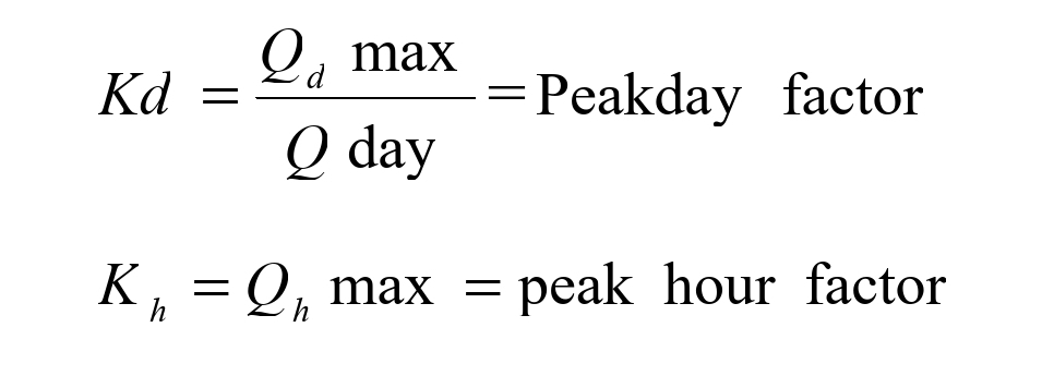
- Maximum Daily Demand, Qd max = the result of the multiplication of the average daily demand by the peak day factor Kd which represents the consumption of the day in the year in which the maximum consumption is registered.
- Peak Hour Demand, Qh max = the result of the multiplication of the maximum daily demand by the peak hour factor Kh which represents the peak hour flow during the day with maximum consumption.
Summary
For design purposes, the peak factor shall be selected under consideration of the size and kind of scheme and services required.
Generally the main from the intake is dimensioned to meet the peak day demand. For gravity schemes, this means a main designed for a flow for 24 hours, while for a pumping main the design flow is according to the pumping hours decided.
1.8.7 Variation in the Rate of Consumption
The average rate of supply per capital is in fact the mathematical average taken over an average year. Thus if Q is the total quantity of water supplied to a population ‘p’ for 365 days, then the average rate of daily consumption ‘q’ is given by:
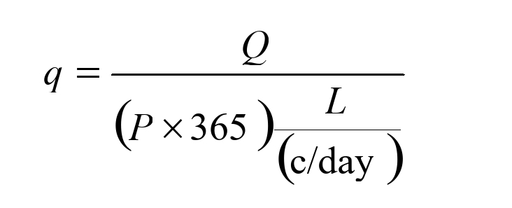
The type of natural variations of demand of which ‘q’ is an average is given below
- Daily Variation
The consumption of water is not uniform throughout the day.
Generally, two peak periods of demand are observed, one in the
morning and one in the evening.
The maximum intensity of demand which occurs in the morning is
about 50% more than the average demand for the day.
- Peak Factors
1.9 Selection of Water Demand
The selection of water demand in the design area includes:
a) Estimation of actual water requirements at present.
b) Addition of water demand in the future based on assumptions on developments. Thus the design demand for water supply will be (a + b).
1.10 Water Pressure
In order to avoid bursting and leakages in the water supply system as well as undersigned noises and pressure shocks, the pressure in the main pipe should be restricted to not more than 60m pressure head for gravity main and about 105m pressure head for rising main and for static pressure at domestic point should be not less than 5m head.
1.11 Water Quality
Water quality should be within the international standards or criteria set by WHO. For rural water supplies, the revised Tanzania temporary standards can be used. Appropriate treatment plants should be designed for all surface water sources.
1.12 Design Period
Is the period in which the project’s long-term projected demands are estimated for a least-cost project. The design period of the project is categorized as short-term 5yrs, future 10yrs, and ultimate period 20yrs.
The design period of this project is 20yrs. In demand, forecast precautions should be taken to avoid overestimating or underestimating the water demand. Overestimation of demand may lead to incurring unnecessary costs. On the other hand for underestimation, more time should be spent on-demand analysis and projections.
Average daily demand is the result of adding together domestic, agriculture, livestock, public institution, industries, commercial, fire demand, and losses. (source: Ministry of Water and Irrigation (July 1997) Design Manual).
Also Read: Best CAD Software For Architects | All You Need to Know
1.13 Air Valves and Washouts
The air valve can be placed in the main lines at higher points of the pipeline in order to release accumulated air during operation ( Airlock ). However, in flat areas, it is preferable to provide an air valve every 1000 metres intervals. While washout should be at all low points of the pipeline.
1.14 Pipe Laying Across the River/ Stream
Pipes should be laid in well-prepared trenches 0.6m wide by 0.75m deep for pipes up to 100mm in diameter. While for bigger diameters trenches of 0.8m wide by 1.0m deep is required. The pipe should be laid on a prepared level bed cushion of sand or soil that is
free of stones under the pipes, then the backfill material should be free of stones.
In case of road crossing or river, special care should be taken. A minimum of 1.0m covers should be provided in road crossing but it is more advantageous to use sleeves of DI, CI, or MS pipes.
The cover and its protection should be up to 3m beyond the width of the road on both sides. For river crossing the main pipe should be laid 1.0m below the river bed covered by a concrete cover, where it is not possible to lay the pipe below the river bed, the pipe can be laid over the river by constructing the supporting pillars (anchor blocks) at the river bank where the flood level will not reach the pipe level. Source: Water Supply And Sanitary Engineering, 2nd Edition.
1.15 Choice of Pipe Materials
Choice of pipe material should be done based on quality, durability, strength, and price point of economic view, due to the fact that the plastic pipes are to be laid in preference of galvanized steel pipes as are cheaper.
Where the soil condition does not allow e.g. pressure requirements of high-class pressure pipes such as GS are used for large and small sizes respectively. GS pipes must be used in intakes, tanks, and brake pressure tanks nevertheless GS pipes are used in road crossings, river crossings,s and places whereby any means of the pipes are to be exposed over the ground.
Pipes are available in various materials, sizes, and classes of pressure. The common pipe materials are: –
- Polyvinyl chloride (PVC)
- Polythene (PE)
- Galvanized steel pipe (GS)
- Ductile iron (DI)
- Cast iron (CI) etc
Selection of pipe materials should be conducted based on economical views i.e. quality cost durability and strength, For instance, it is economical to select plastic pipes rather than galvanized steel pipes which are expensive except where pressure is extremely high.
Also, GS pipes are normally used where pipes are by any means exposed over the ground or when the locality comprises rocks or at the road crossing, river crossing, intake, storage tanks, etc.
1.15.1 Pipe classes and ranges in pressure
Pipes are classified according to their capacity to withstand pressure whereas plastic pipes (PVC, polythene) are classified from classes A, B, C, etc. class A has the lowest capacity, and steel pipes are classified as medium and heavy-duty, the heavy-duty class has a high capacity to withstand pressure.
The following table shows the normal working pressure of different pipe classes.
Table 5: Working Pressure of different pipe classes
| Material | Class | Pressure range (Meter) |
| Steel | Medium | 0-105 |
| Steel | Heavy duty | 105-240 |
| PVC/POLY | A | 0-30 |
| PVC/POLY | B | 30-60 |
| PVC/POLY | C | 60-90 |
| PVC/POLY | D | 90-120 |
| PVC/POLY | E | 120-150 |
1.15.2 Flows in Pipes
The empirical Hazen- William formula has the advantage of simplicity for determining the flow of raw or potable water at normal temperature; it can be relied upon to give results of sufficient accuracy for all practical purposes
Table 6: Shows pipe sizes and recommended velocity
| Pipe size (mm) | Suggested Velocity m/s |
| Pipe 50 -100 diameter | 0.6 -1.0 |
| Medium size 150 -250 diameter | 1.0 -1.5 |
| Pipe 300 -500 diameter | 1.2 -2.0 |
| >than 500 diameter | Recommended by the manufactures |
We hope this article helped you learn about Water Supply Design | Water Sources and Storage Tanks. You may also want to learn about What is the Function of Buildings? , 21 Types of Engineering To Know In 2023, Types of Glasses for Construction, and Problem Solving | All Skills You Need To Know
If you liked this article, please Join WebsiteForEngineers on Telegram, and you can also find us on Pinterest, Twitter, and Facebook.