
Floor and Decor are the terms used for flooring, which means the start and finish of the floor. The floor is a horizontal part of the structure that divides the building into stories.
It may consist of joist-supported wood planks or panels, decking or panels supported by wood or steel beams, a slab of stone or concrete on the ground, or a reinforced-concrete slab carried by concrete beams and columns.
While Decor refers to the process of making something more attractive, or to the items that are used to make something more attractive.
For this post, Decor means the process of finishing the floor in various styles and materials which can be timber, concrete, etc.
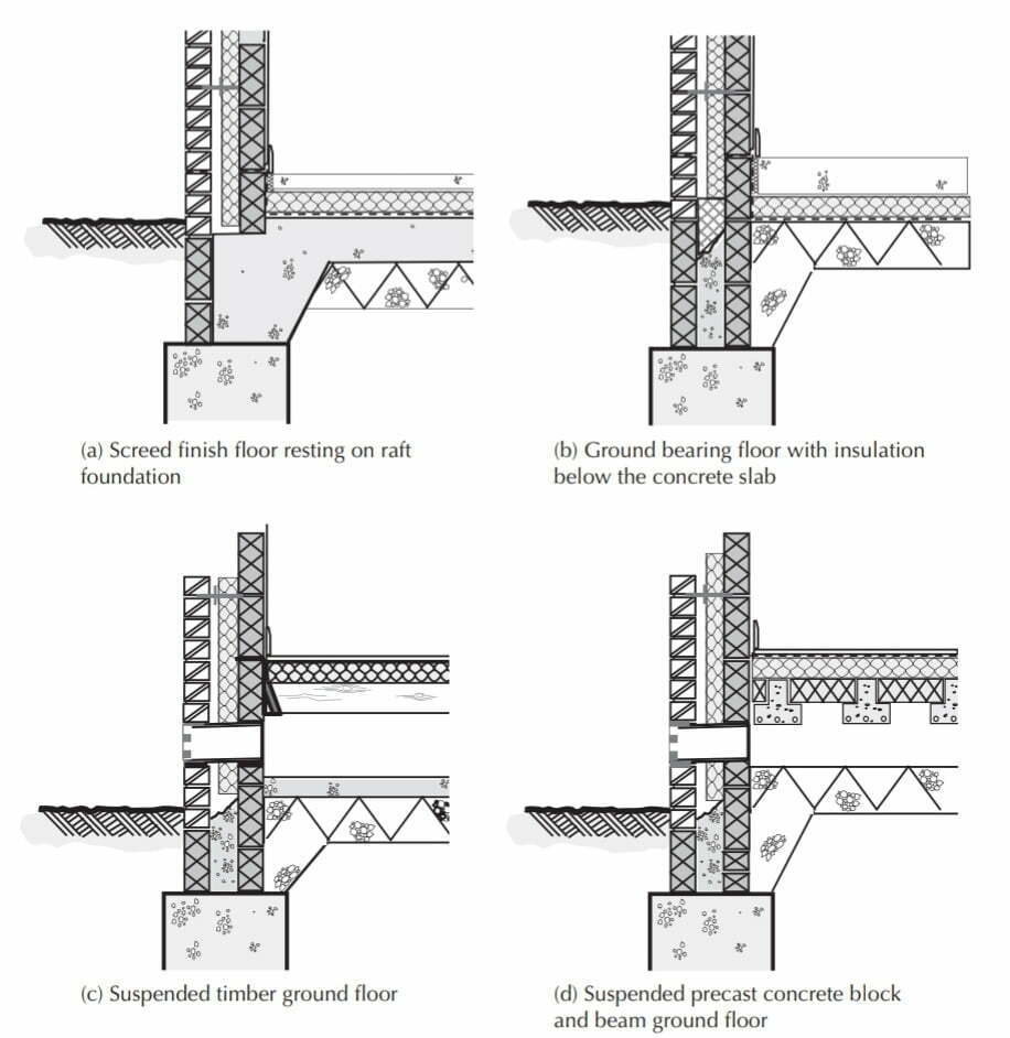
Concrete and timber are the two materials most used for the construction of ground and upper floors, the choice of one over another is determined largely by the span required and the required performance in terms of fire safety and the resistance to the passage of heat and sound. Ground and upper floors constructed of Concrete or timber are described in this article. The figure above provides examples of some common types of floor construction.
1.1 Functional requirements
The functional requirements of a floor are:
- Strength and stability
- Resistance to weather and ground moisture
- Durability and freedom from maintenance
- Fire safety – resisting spread and passage of fire
- Fire safety – providing stable support for occupants to evacuate
- Resistance to the passage of heat
- Resistance to the passage of sound
Strength
The strength of a floor depends on the characteristics of the materials used for the structure of the floor, such as timber, steel, or concrete. The floor structure must be strong enough to support safely the dead load of the floor and its finishes, fixtures, partitions, and services, and the anticipated imposed loads of the occupants and their movable furniture and equipment. BS 6399: Part 1 is the Code of Practice for dead and imposed loads for buildings. Where imposed loads are small, as, in single-family domestic buildings of not more than three stories, timber floor construction is usual. The lightweight timber floor structure is adequate for small loads over small spans. Precast concrete block and beam flooring offer an economical and quick alternative to timber floors. For larger imposed loads and wider spans, a reinforced concrete floor is used, both for strength in support and also for resistance to fire. Approved Document A includes tables of recommended sizes and spacing for softwood timber floor joists of two strength classes, for various dead loads and spans.
Stability
A floor is designed and constructed to serve as a horizontal surface to support people and their furniture, equipment, or machinery.
The floor should have adequate stiffness to remain stable and horizontal under the dead load of the floor structure and such partitions and other fixtures it supports and the anticipated static and live loads it is designed to support.
The floor structure should also support and accommodate services either in its depth or below or above the floor, without affecting its stability. Solid ground and basement floors are often built off the ground from which they derive support.
The stability of such floors depends, therefore, on the characteristics of the concrete under them. Upper or suspended floors are supported by walls or beams and should have adequate stiffness to minimize deflection under load.
Under load, a floor will deflect and bend, and this deflection or bending should be limited to avoid cracking of rigid finishes such as plasterboards, which are attached to the ceiling directly below the floor.
Resistance to weather and ground moisture
The requirements of the Building Regulations for the resistance of the passage of moisture through ground floors to the inside of buildings are described as follows.
Durability and freedom from maintenance
All floors should be durable for the expected life of the building and require little maintenance or repair. The durability and freedom from maintenance of floor finishes will depend on the nature of the materials used and the wear to which they are subject.
Fire safety
Suspended upper floors should be so constructed as to provide resistance to fire for a period adequate for the escape of the occupants from the building. The notional periods of resistance to fire, from ½ to 4 hours, depending on the size and use of the building, are set out in the Building Regulations.
Resistance to the passage of heat
A floor should provide resistance to the transfer of heat where there is normally a significant air temperature difference on the opposite sides of the floor. This would include any building which was heated but would not include some external buildings, such as garages.
Resistance to the passage of sound
Upper floors that separate dwellings (party floors), or separate noisy from quiet activities, should act as a barrier to the transmission of sound.
The comparatively low mass of a timber floor will transmit airborne sound more readily than a high-mass concrete floor, so party floors between dwellings, for example, are generally constructed of concrete.
The hard surfaces of the floor and ceiling of both timber and concrete floors will not appreciably absorb airborne sound, which will be reflected.
The sound absorption of a floor can be improved by introducing a soft absorbent material such as carpet or felt. Absorbent tiles and finishes can also be used on walls and ceilings to reduce echo effects caused by sound reflecting and bouncing back off hard surfaces.
When upgrading existing buildings, sound insulation can be improved by filling between timber joists and sealing voids, or by constructing a floating floor, or suspended floor, both of which introduce breaks between the floor surface and the structural floor.
Where cavities exist between the floor surface and the structural floor, sound-insulating materials can be introduced to add further sound reductions. Floating floors prevent the impact sound from foot traffic from transferring to the main structure. Specially designed acoustic-based resilient floor coverings that reduce impact sound are also available.
1. 2 Ground-supported concrete slab
A typical Concrete ground-supported slab is shown in the Figure below. It is general practice first to build the external and internal loadbearing walls from the Concrete foundation up to the level of the damp-proof course (DPC).
The hardcore bed and the concrete slab are then spread and leveled within the area created by the walls. If the hardcore is spread and consolidated over the whole area of the ground floor, into and around excavations used to construct foundations, and where the soft ground has been removed, there should be very little settlement of the ground that supports the floor slab.
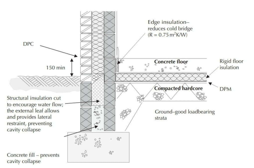
the cavity to prevent a cold bridge.
The hardcore should be thoroughly consolidated using a vibrating plate or roller. Settlement cracking in ground floor slabs is often due to inadequate hardcore beds, poor filling of excavation for trenches, or ground movement due to moisture changes (swelling or shrinkage of clay soils).
Where appreciable settlement is anticipated it is best to reinforce the slab and build it into walls as a suspended reinforced concrete slab. The gap below the floor will allow clay soils to swell and contract without causing damage to the structural floor.
Hardcore
Hardcore is the name given to the infill of materials such as crushed and graded bricks, stone, or concrete, which are hard and do not readily absorb water or deteriorate. Hardcore should be spread until it is level, then compacted using a mechanical vibrating plate or roller. The hardcore provides a stable bed for the concrete slab; this hardcore bed is usually 100–300 mm deep.
The materials used for hardcore should be chemically inert, not appreciably affected by water, and should be free from water-soluble sulfates.
The materials used for hardcore are:
- Brick or tile rubble. Clean, hard-broken brick or tile crushed and graded. Bricks should be free of plaster and wood. On wet sites, the bricks should not contain appreciable amounts of soluble sulfate.
- Concrete rubble. Clean, broken, well-graded concrete is a good material for hardcore. The concrete should be free from plaster, wood, or other building materials.
- Gravel and crushed hard rock. Clean, well-graded gravel and crushed hard rock are both excellent but somewhat expensive materials for hardcore.
- Chalk. Broken chalk is a good material for hardcore providing it is protected from expansion due to frost. Once the site concrete is laid it is unlikely to be affected by frost.
- Road plannings. When roads are resurfaced the top of the road is planned off. The plannings provide a very good strong hardcore, which binds together when compacted.
Blinding layer
It was common for hardcore to have a blinding layer of dry Concrete or sand, 50 mm deep, placed on it before the concrete was laid. The purpose of this was to prevent the wet Concrete from running down between the lumps of broken brick or stone and to form a smooth bed for the damp-proof membrane (DPM).
Now that hardcodes are well graded with a mixture of fine and course material, when the hardcore is adequately compacted the surface finish is relatively smooth and level; thus, a blinding layer is unnecessary.
Where a reinforced cage is to be used within the concrete slab it is useful to have a level surface from which to work. Thus blinding may be used so that the reinforcement cage can be easily constructed on the level surface, and properly spaced and positioned off the concrete blinding.
Also Read: What is Mortar? | Uses and Tests
Damp-proof membrane
A requirement of the Building Regulations is that floors shall adequately resist the passage of moisture to the inside of the building. Concrete is permeable to moisture; therefore, it is necessary to use a DPM under, in, or on top of ground-supported concrete floor slabs as an effective barrier to moisture rising from the ground (Figure 4.3).
The membrane should be continuous with the DPC in the walls to prevent moisture from rising between the edges of the concrete slab and walls. A DPM should be impermeable to water in either liquid or vapor form and be tough enough to withstand possible damage during the laying of screeds, concrete, or floor finishes. The position of the DPM will vary in accordance with the proposed method of construction.
DPM below concrete
The membrane is spread on a blinding layer or directly onto the hardcore if well-graded and smooth. The edges of the membrane are turned up the faces of the external and internal walls so that they may unite and overlap the DPC in the wall. The membrane should be spread with some care to ensure that it is not punctured and that the edge upstands are kept in place as the concrete is subsequently laid.
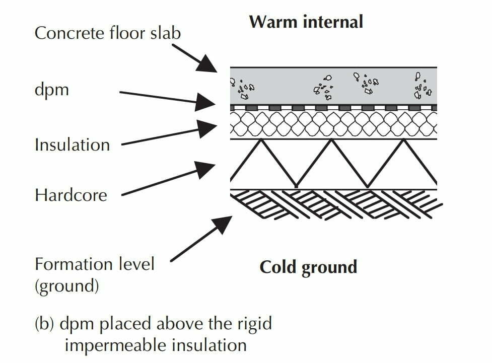
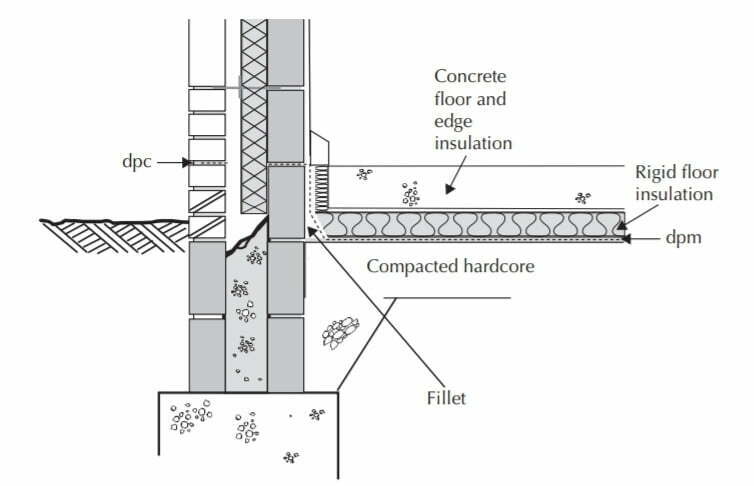
The advantage of a DPM under the concrete is that it will be protected from damage during subsequent building operations. The concrete remains dry and protected from impurities. However, unless the concrete is likely to suffer a chemical attack, the dampness caused by groundwater is not a cause for concern and the DPM can just as easily be placed on top of the concrete. When rigid impermeable insulation is used the DPM should be placed on the warm side (internal side) of the insulation, reducing the possibility of interstitial condensation (Figure below).
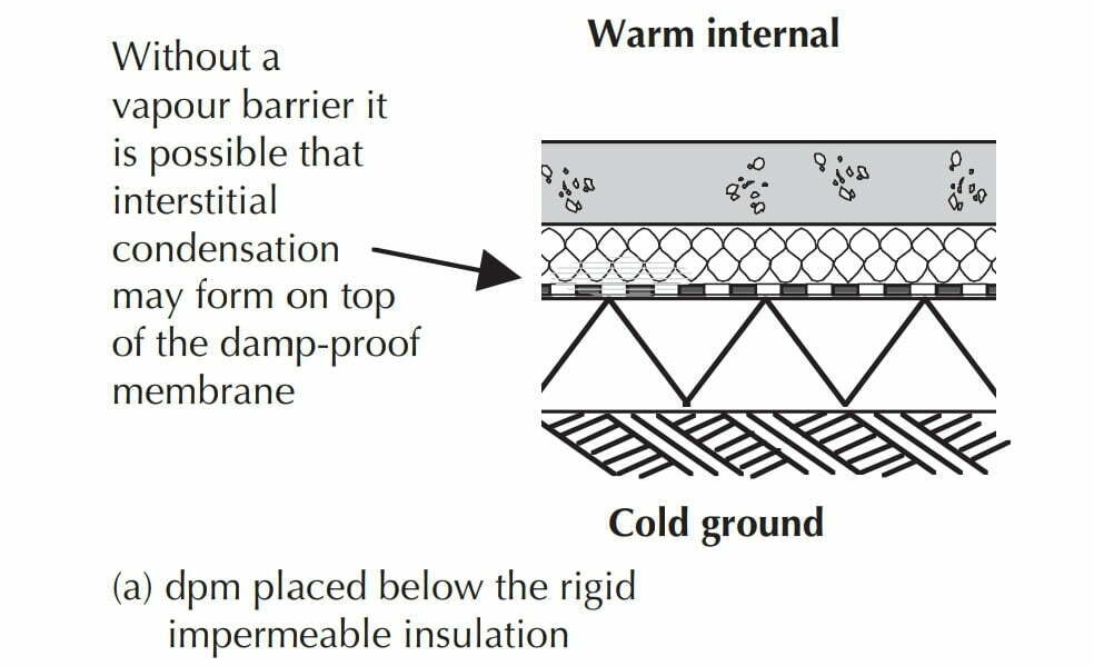
Although concrete does have a level of natural resistance to the passage of moisture poor workmanship may mean that water vapor can penetrate the structure. Where underfloor heating is used the membrane should be under the concrete (Figure below).
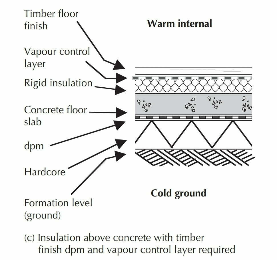
If the insulation is placed on top of the concrete and a timber finish is applied to the surface a vapor control layer must be used (Figure below). If a vapor barrier is not used, warm moist air will penetrate through the timber finish to the cold side of the insulation and form condensation on top of the DPM. If the insulation is permeable then the DPM must go below the insulation and a vapor barrier may be used on top of the insulation.
Surface DPM
Floor finishes such as pitch mastic and mastic asphalt that are impermeable to water can serve as a combined DPM and floor finish. These floor finishes should be laid to overlap the DPC in the wall to seal the joint between the concrete and the wall. Where hot soft bitumen or coal-tar pitch are used as an adhesive for woodblock floor finishes, the continuous layer of the impervious adhesive can serve as a waterproof membrane.
DPM below a floor screed
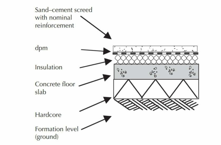
An alternative method is to place the DPM between the floor screed and the thermal insulation, as illustrated in the Figure below. At the junction of the wall and floor, the membrane should overlap the DPC in the wall. An advantage of positioning the DPM above the insulation is that it can be used to secure the upstand edge insulation in place while concrete is being placed. If the DPM is laid below the insulation it is necessary to spread a separating layer over the insulation to prevent wet screed from running into the joints between the insulation boards.
The separating layer should be building paper or a 500-gauge polythene sheet. To avoid damage to the insulation layer and the DPM it is necessary to take care in tipping, spreading, and compacting wet concrete or screed. Scaffold boards should be used for borrowing and tipping concrete.
Materials used for the DPM
The materials used as DPM must be impermeable to water both in liquid and vapor form and also be sufficiently robust to withstand accidental (puncture) damage to the membrane during building operations.
Polythene and polyethylene sheet
Polythene or polyethylene sheet is commonly used as a DPM with oversite concrete for all but severe conditions of dampness. These sheets should be chemically inert and not be affected by alkalis and acids present in the subsoil. It is recommended that the sheet should be at least 0.25 mm (250μm) thick (1200 gauge).
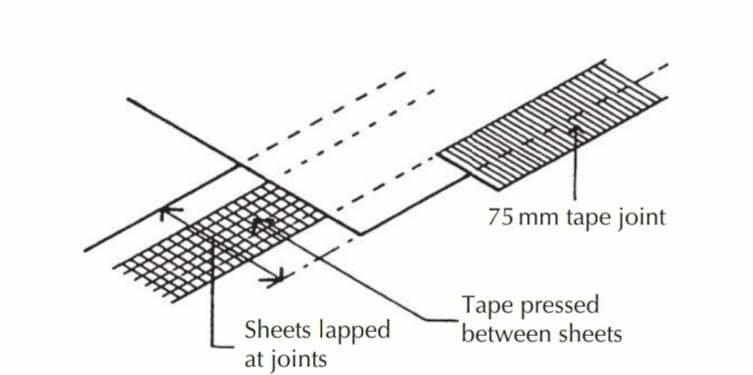
Sheets are also available in 300 and 500μm thicknesses and are supplied in rolls 4 m wide by 25 m long. The sheets are spread over the blinding and lapped 150 mm at joints and continued across surrounding walls,
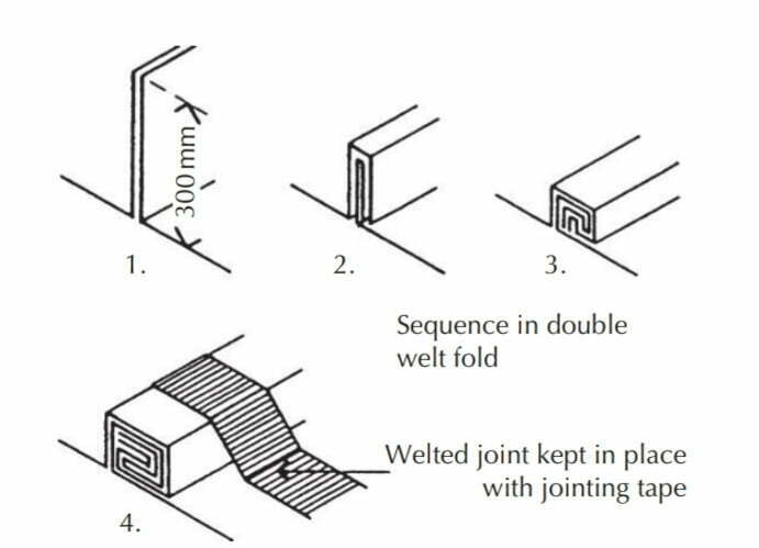
under the DPC for the thickness of the wall. Where site conditions are reasonably dry and clean, the overlap joints between the sheets are sealed with mastic or mastic tape between the overlapping sheets, and the joint is completed with a polythene jointing tape as illustrated in the Figure below.
For this lapped joint to be successful the sheets must be dry and clean or the jointing tape will not adhere to the surface of the sheets. Where site conditions are too wet to use mastic and tape, the joint is made by welting the overlapping sheets with a double welted fold as illustrated in the Figure below, and this fold is kept in place by weighing it down with bricks or securing it with tape until the screed or concrete has been placed.
The sheet should be used so that there are only joints one way as it is impractical to form a welt at junctions of joints.
Where the level of the DPM is below that of the DPC in walls, it is necessary to turn it up against walls so that it can overlap the DPC or be turned over as DPC as illustrated in the Figure below.
To keep the sheet in place as an upstand to walls it is necessary to keep it in place with bricks or blocks laid on the sheet against walls until the concrete has been placed and the bricks or blocks removed as the concrete is run up the wall. At the internal angle of walls, a cut is made in the upstand sheet to facilitate making an overlap of sheets at corners.
Penetrations for service pipes will need to be sealed using proprietary Top Hat units and sealed using double-sided sealing tape in accordance with the manufacturer’s instructions.
Manufacturers also provide guidance on repairing accidental punctures to the DPM. All membranes must be covered (e.g., with a screed) as soon as possible after laying to prevent accidental damage and to protect the membrane from the damaging effect of sunlight.
Recycled content membranes
Increasingly the manufacturers of damp-proofing materials are offering products manufactured entirely from post-use waste. Reprocessed and recycled polyethylene DPMs are available that comply with BS EN 13967:2004 ‘Flexible sheets for waterproofing and have similar or better performance compared with traditional DPMs.
Hot pitch or bitumen
A continuous layer of hot applied coal-tar pitch or soft bitumen is poured on the surface and spread to a thickness of not less than 3 mm. In dry weather, a concrete binding layer is ready for the membrane 3 days after placing. The surface of the concrete should be brushed to remove dust and primed with a solution of coal-tar pitch or bitumen solution or emulsion. Properly applied pitch or bitumen layers serve as an effective DPM both horizontally and spread up inside wall faces to unite with DPCs in walls.
Bitumen solution, bitumen/rubber emulsion, or tar/rubber emulsion
These cold-applied solutions are brushed onto the surface of the concrete in two or three coats to a finished thickness of not less than 2.5 mm, allowing each coat to dry and harden before the next is applied. Bitumen-based solvent-free emulsion liquid DPMs are suitable for horizontal and vertical application given the material’s adhesive, elastic, and waterproofing properties.
Bitumen sheet
Sheets of bitumen with hessian, fiber, or mineral fiber base are spread on the concrete oversite or on blinding of stiff concrete below the concrete, in a single layer with the joints between adjacent sheets lapped 75 mm. The joints are then sealed with a gas torch, which melts the bitumen in the overlap of the sheets sufficient to bond them together. Alternatively, the lap is made with hot bitumen spread between the overlap of the sheets, which are then pressed together to make a damp-proof joint. The bonded sheets may be carried
across adjacent walls as a DPC, or up against the walls, and then across as DPC where the membrane and DPC are at different levels.
Mastic asphalt or pitch mastic
These materials are spread hot and finished to a thickness of at least 12.5 mm. This expensive DPM is used where there is appreciable water pressure under the floor and as ‘tanking’ to basements.
1.3 Suspended concrete floor slabs
Suspended concrete slabs or block and beam floors are used where the ground:
- Slopes
- Has poor or uncertain bearing capacity
- Is liable to volume change (swells and shrinks)
In such situations, it may be wise to form the ground floor as a suspended reinforced concrete slab or to use a block and beam floor, supported by external and internal loadbearing walls, which are independent of the ground. Suspended concrete floors can be constructed using:
- Precast reinforced concrete planks or slabs
- Block and beam floor systems or
- In situ reinforced concrete slabs
T-beam method
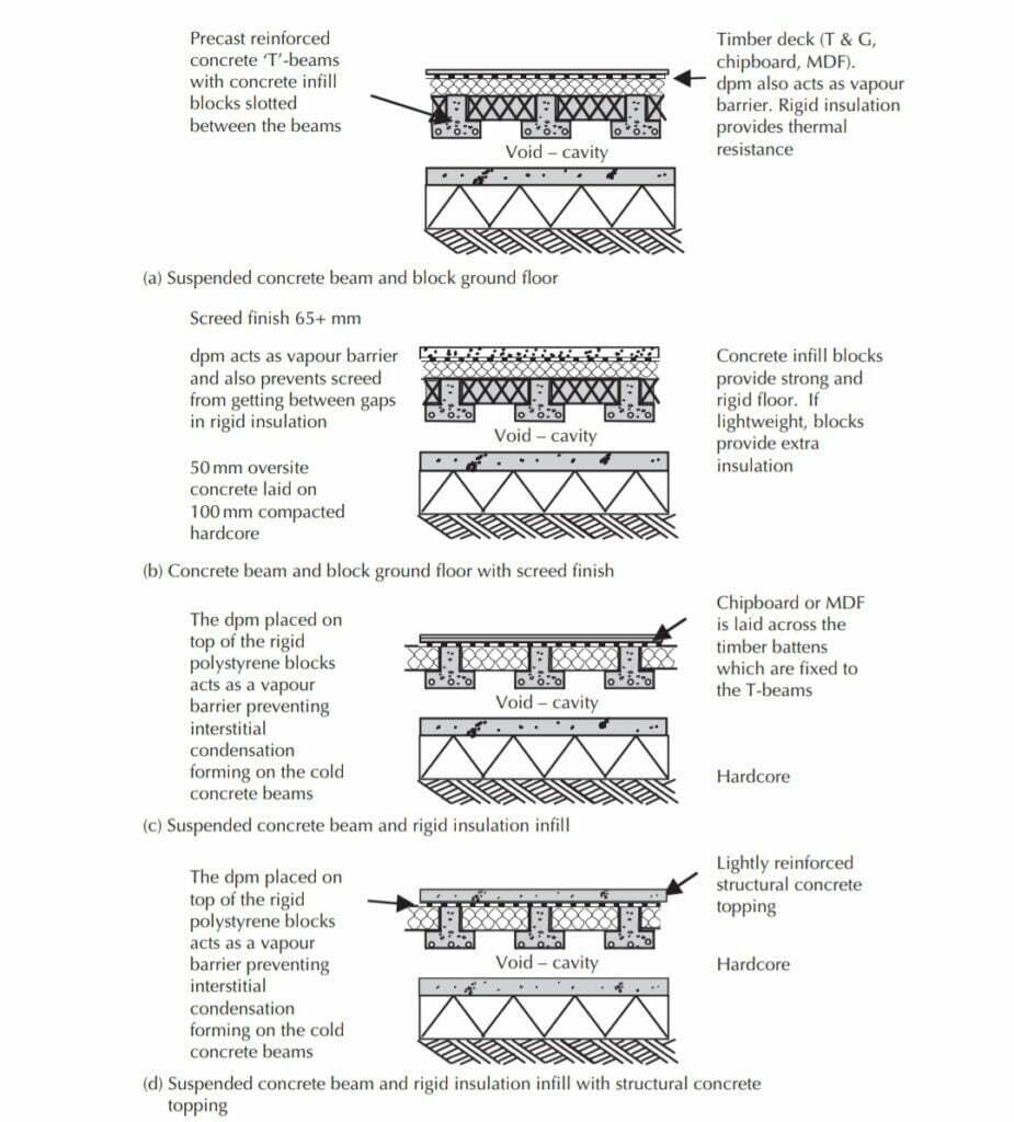
It is common practice to construct raised concrete floors using the concrete block and inverted T-beam method (see Section 4.6, ‘Reinforced Concrete Upper Floors’). Brick or concrete block sleeper walls are built off the ground slab to support the concrete ‘T’-beams. The precast inverted T-beams are located on the perimeter walls and internal sleeper walls; concrete infill blocks are then inserted between the beams.
Spacing between sleeper walls is dictated by an economical span for the inverted T-beams. A concrete topping or screed is spread and leveled over the precast concrete units. Where there is a likelihood of an accumulation of gas building up in the space below the floor, the space should be at least 150 mm clear, and cross-ventilation should be provided.
Solid reinforced concrete beams usually shaped like an inverted T in the section are precast to the required length. The depth of the beams is from 130 to 250 mm. The beams are made in lengths of up to 6 m. The T-beams are reinforced with mild steel reinforcing bars to provide adequate support for the deadweight of the floor and anticipated dead and live loads.
Precast lightweight concrete infill blocks are made to fit between and bear on the T-beams. Some of the blocks are hollow (for lightness), although it is now more common to use solid blocks. It is possible to use rigid insulation between the beams instead of concrete blocks (Figure below).
Floor surface
The term floor finish is generally used to describe the material or materials that are applied to a floor surface as a finished surface, such as tiles (see Chapter 10). It is important to distinguish clearly between the level of the structural floor finish (SFF) and the finished floor level (FFL) to avoid confusion on site (Figure below).
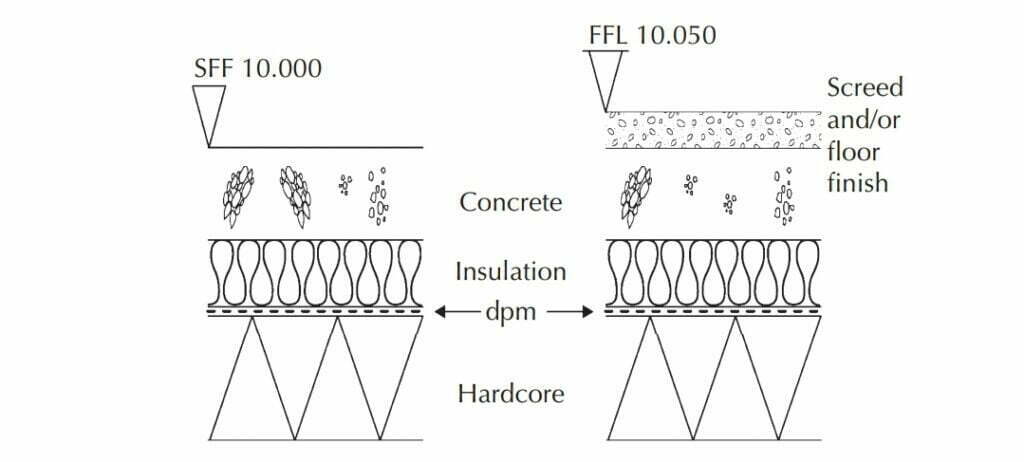
For sheds, workshops, stores, and garages, the SFF of the concrete is sometimes used as the finished floor surface to save the cost of an applied floor finish. Unless finished and sealed correctly, concrete floors have poor resistance to wear, and in a short time the surface of the concrete is ‘dust’. Being a coarse-grained material, concrete cannot be washed clean, and if it becomes stained the stains are permanent.
Extensive areas of a concrete floor may be leveled and finished by power floating. Concrete floors provide a satisfactory base for thicker floor finishes such as mastic asphalt, tiles, and woodblocks. For thin finishes such as plastic, linoleum, rubber sheet, and tile, the more precisely level, smooth surface of a screeded base is necessary. However, with the increasing precision of concrete laying machines that are guided and leveled by lasers, floors can be produced that are level within a tolerance of ±1.5 mm. The use of concrete
laying machines is restricted by access through the building to the floor area and obstructions within the structure.
Also Read: Structural Design Basis | General Guidelines
Floor screeds
The purpose of a floor screed is to provide a level surface to which a floor finish can be applied. The word screed is used to describe the wet sand–cement mix that is first laid across the length and width of the floor. If screed finishes are to be used over large areas it may be necessary to lay the screed in strips or bays. The screed strips or bays are carefully leveled in both directions to set out a precise level finish. The main bulk of the mix (which is semi-dry) is then spread and leveled between the screeds.
Generally, screed mixes have just sufficient water for hydration; the screed mixes do not have the wet workable properties of concrete typically used in floor construction. Too much water will cause the screen to slump. The screed has a composition such that when it is formed to the level required it remains in position.
This is not the same for self-leveling screeds or compounds which are much more fluid in composition and are poured in thin layers onto the floor, lightly floated, and then left to level out.
The thickness of the screed and the mix of cement and sand depend on the surface on which the screed is laid. The cement-rich mix used in a screed will shrink as it dries; thus, the thinner the screed, the more rapidly it will dry and the more it will shrink and crack.

On the majority of building sites, the concrete ground and upper floors are cast and roughly leveled as a working platform for subsequent building operations. To avoid damage to screeded surfaces that will serve as a finished floor surface or as a level base or substrate for applied floor finishes it is usual to lay a screed after the concrete floor has dried and hardened.
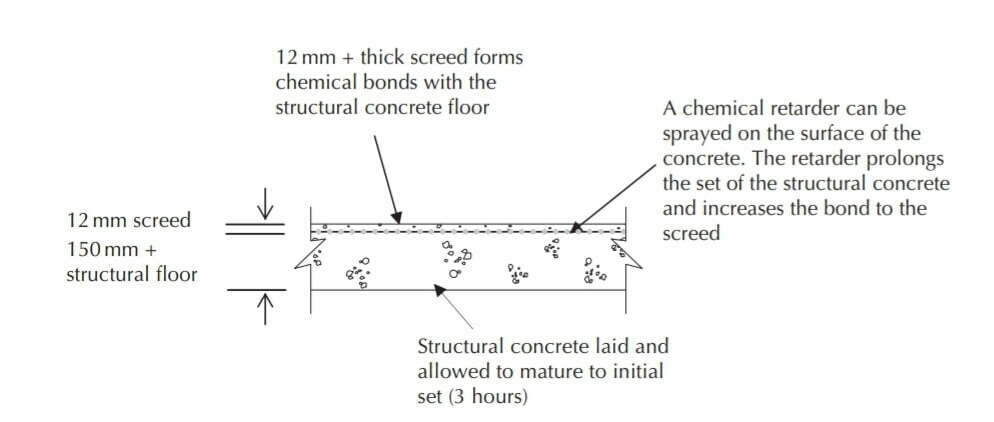
Bonded screeds
Where it is practical to lay a screed on a concrete base within 3 hours of placing the concrete it will bond strongly to the concrete. The screed will also dry slowly with the concrete so that drying shrinkage and cracking of the screed relative to that of the concrete will be minimized. For this monolithic construction of the screed, a thickness of 12 mm screed will suffice (Figure below).
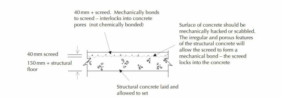
Semi-bonded screeds
A screed laid on a concrete base that has set and hardened should be at least 40 mm thick. To provide a good bond between the screed and the concrete, the surface of the concrete should be hacked by mechanical means, cleaned and dampened, and then covered by a thin grout, or wet mix, of water and cement before the screed is laid. With a good bond to the concrete base, a separate screed at least 40 mm thick will dry sufficiently slowly to avoid serious shrinkage cracking (Figure below).
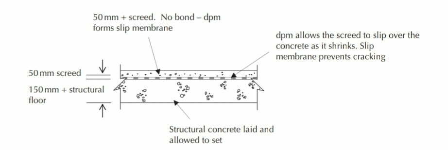
Independent or unbonded screeds
Where a screed is laid on an impermeable DPM there will be no bond between the screed and the concrete base so that the drying shrinkage of the screed is unrestrained. So that the screed does not dry too rapidly and suffer shrinkage cracking, the screed in this unbonded construction should be at least 50 mm thick, reinforced with light mesh (Figure below).
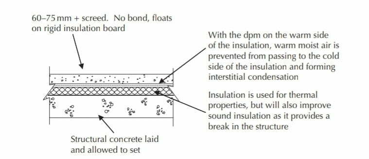
Floating floor–screed
A screed laid on a layer of compressible thermal or sound insulating material should be at least 65 mm thick for domestic buildings and 75 mm for other buildings if this floating construction is not to crack due to drying shrinkage and the deflection under loads on the floor (Figure below).
For screeds up to 40 mm thick, a mix of cement and clean sand in the proportions by weight of 1 : 3 to 1: 4½ is used. The lower the proportion of cement to sand, the less drying shrinkage. For screeds over 40 mm thick a mix of fine concrete is often used in the proportions of 1: 1½: 3 of cement, fine aggregate, and coarse aggregate with a maximum of 10 mm for the coarse aggregate.
The screed should be mixed with just sufficient water for workability. The material is spread over the surface of the base to the required level and then it is finished with plastic or steel float. The screed should be cured, that is, allowed to dry out slowly over the course of several days. Curing prevents the water needed for hydration from evaporating out of the screed. The water within the wet concrete mix can be held in place by covering the screed with polythene sheeting, damp hessian, or a liquid chemical curing agent (which is sprayed onto the surface of the screen). Premixed cement screed materials are available and can be delivered to the site with polymer or steel fiber for reinforcement.
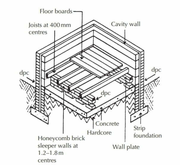
1.4 Suspended timber ground floors
A suspended (or raised) timber ground floor is constructed as a timber platform of boards nailed across timber joists bearing on ½ brick (B) thick sleeper walls. The raised timber floor is formed inside the external walls and internal walls, as illustrated in the Figure below.
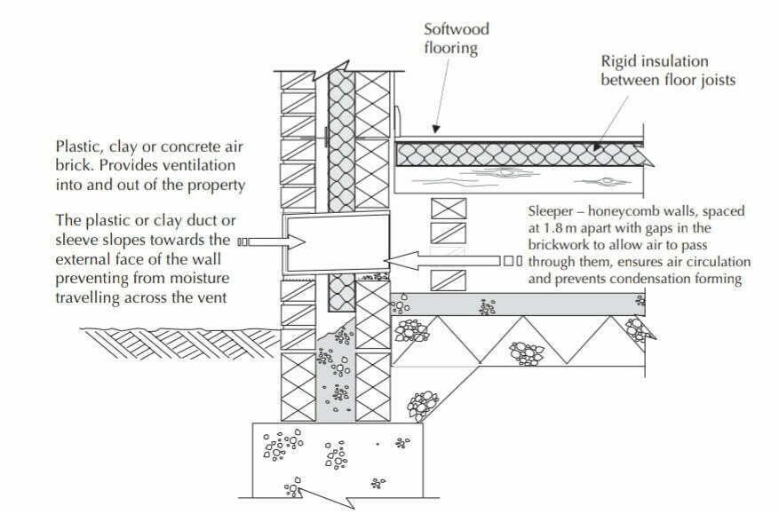
Sleeper walls
Sleeper walls are ½ B thick and built directly off the site concrete up to 1.8 m apart (Figure 4.14). These sleeper walls are generally built at least three courses of bricks high and sometimes as much as 600 mm high. The walls are built honeycombed to allow free circulation of air below the floor, the holes in the wall being ½ B wide by 65 mm deep, as illustrated in the Figure below. The guidance in Approved Document C requires a space of at least 75 mm from the top of the concrete to the underside of a wall plate and at least 150 mm to the underside of the floor joists.
Ventilation
The space below the floor is usually ventilated by inserting air bricks, made of terracotta or plastic, in the walls below the floor so that air from outside the building can circulate at all times under the floor. This is to prevent stagnant air and the possibility of dry rot from developing under the floor. Airbrick dimensions are 215 × 65, 215 × 140 or 215 × 215 mm.
These bricks are built into external and internal walls for each floor to provide 1500 mm of ventilation for each meter run of wall. The bricks are built just above ground level and below the floor.
Wall plate
A wall plate is a continuous length of softwood timber that rests along the length of a wall. The function of a wall plate for timber joists is twofold. It forms a firm level surface on which the timber floor or roof joists can bear and to which the floor joists can be nailed. The wall plate spreads the point loads from joists uniformly along the length of the wall below. The plate makes it considerably easier to fix floor and ceiling joists to the wall.
A wall plate is usually 100 × 75 mm timber and is laid on its widest face so that there is a 100 mm surface width on which the timber joists bear. A DPC should be laid on top of the sleeper walls under the wall plate to prevent any moisture from rising through the sleeper walls to the timber floor.
Floor joists
Floor joists are rectangular sections of sawn softwood timber from 38 to 75 mm thick and from 75 to 225 m deep, spaced from 400 to 600 mm apart. The minimum bearing for floor and roof joists is 35 mm (Approved Document A).
The span of a joist is the distance measured along its length between walls that support it. The sleeper walls built to support the joists are usually 1.8 m apart or less; thus, the span of the joists is 1.8 m or less. The best method of supporting the ends of the joists at external walls and at internal brick partitions is to build a honeycombed sleeper wall some 50 mm away from load-bearing walls to carry the ends of the joists. The sleeper wall is built away from the main wall to allow air to circulate through the holes in the honeycomb of the sleeper wall. The ends of the joists are positioned so that they are 50 mm clear of the inside face of the wall.
From a calculation of the dead and imposed loads on the floor the most economical size and spacing of joists can be selected from the tables in Approved Document A and from this the spacing of the sleeper walls to support the joists can be found. Similarly, the thickness of the floorboards to be used will determine the spacing of the joists; the thicker the board, the greater the spacing of the joists.
Timber floorboards, chipboard, medium-density fiberboard (MDF), or plywood boards are laid across the joists and are then screwed or nailed to them to form a firm, level floor surface. Screwing the boards to the joists tends to be more time-consuming compared to nailing, but it allows ease of access, e.g., to electrical wiring and pipes positioned in the floor void.
Floor surface
Floorboards for timber floors are usually 16, 19, 21, or 28 mm thick and 65, 90, 113 or 137 mm wide and up to about 5 m in length. The common way of cutting boards is with a projecting tongue on one edge and a groove on the opposite edge of each board.
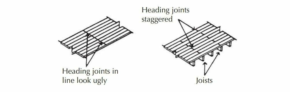
The tongued and grooved (T & G) boards are laid across the floor joists and cramped together. The boards, as they are cramped up, are screwed or nailed to the joists with two screws or nails to each board bearing on each joist. The joint between the end of one board and the end of another is described as the heading joint.
The heading joints in floorboards should always be staggered in some regular manner. Obviously, the heading joint ends of boards must be cut so that the ends of both boards rest on a joist to which the ends are nailed. A usual method of staggering heading joints is illustrated in the Figure below. T & G boards provide an attractive floor finish, which can be finished with stain or varnish to improve durability and appearance.
The recommendation in Approved Document A is that T & G boards screwed or nailed to joists spaced at up to 500 mm should be at least 16 mm finished thickness and at wider spacing up to 600 mm, 19 mm finished thickness. Boards of compressed wood chips, and chipboards, are commonly used today as a substitute for T & G boards. The use of a large T & G chipboard minimizes joints and allows for more rapid construction. The boards are nailed or screwed to the timber joists. These boards will need to be covered with an applied floor finish, such as carpet or vinyl sheet, to provide an attractive finish.
Thermal insulation
To meet the requirements of the Building Regulations for resistance to heat transfer through ground floors it may be necessary to insulate suspended timber ground floors. The most practical way of insulating a suspended timber ground floor is to fix a mineral wool roll, mat or quilt, or semi-rigid slabs between the joists.
Rolls or quilts of loosely felted glass fiber or mineral wool are supported by a mesh of plastic that is draped over the joists and stapled in position to support the insulation. Semi-rigid slabs or batts of fiberglass or mineral wool are supported between the joists by nails or battens of wood nailed to the sides of the joists.
1.5 Resistance to the passage of heat
Approved Document L includes provision for the insulation of ground floors. To reduce heat losses through thermal bridges around the edges of solid floors and so minimize problems of condensation and mold growth, edge insulation should be used, particularly where the wall insulation is not carried down below the ground floor slab.
Edge insulation is formed as a vertical strip between the edge of the slab and the wall as illustrated in Figure 4.18. The depth (width) of the strips of edge insulation is selected so that the whole edge of the concrete floor and screed is insulated.
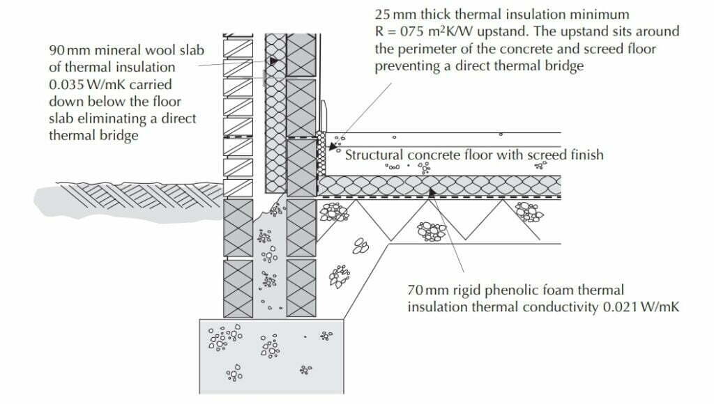
reduce the cold bridge.
Achieving insulation values in different types of floor construction
The only practical way of improving the insulation of a solid ground floor to the required U-value is to add a layer of rigid insulation board with high thermal resistance to the floor. The layer of insulation may be laid below a chipboard or plywood panel floor finish or below a timber boarded finish or below the screed finish to a floor or under the concrete floor slab.
With insulation under the screed or slab, it is important that the density of the insulation board is sufficient to support the load of the floor itself and imposed loads on the floor. A density of at least 16 kg/m3 is recommended for domestic buildings.
The advantage of laying the insulation below the floor slab is that the high-density slab, which warms and cools slowly (slow thermal response) in response to changes in temperature of the constant low-output heating systems, will not lose heat to the ground. With the insulation layer and the DPM below the concrete floor slab, it is necessary to continue the DPM and insulation up vertically around the edges of the slab to unite with the DPC in the wall.
Where the wall insulation is in the cavity, or on the inside face of the wall, it is necessary to avoid a cold bridge across the foundation wall and the edges of the slab. This is achieved by fitting insulation around the edges of the slab or by continuing the insulation down inside the cavity.
Materials for under-floor insulation
Any material used as an insulation layer to a solid, ground-supported floor must be sufficiently strong and rigid to support the weight of the floor or the weight of the screed and floor loads without undue compression and deformation. To meet this requirement one of the rigid board or slab insulants is used. The thickness of the insulation is determined by the nature of the material from which it is made and the construction of the floor, to provide the required U-value.
Some insulants absorb moisture more readily than others and may be affected by ground contaminants. Where the insulation layer is below the Concrete floor slab, with the DPM above the insulation, an insulant with low moisture absorption characteristics should be used. The materials commonly used for floor insulation are mineral wool slabs, extruded polystyrene, cellular glass, and rigid polyurethane foam boards.
1.6 Reinforced Concrete upper floors
Reinforced Concrete floors have better resistance to damage by fire and can safely support greater superimposed loads than timber floors of similar depth. The resistance to fire, required by building regulations for most offices, large blocks of flats, factories, and public buildings, is greater than can be obtained with a timber upper floor; therefore, some form of reinforced Concrete floor has to be used.
The types of reinforced concrete floors that are used for small buildings are self-centering T-beams and infill blocks, hollow beams, and monolithic in situ cast floors. The word centering is used to describe the temporary platform on which in situ cast concrete floors are constructed and supported until the concrete has sufficient strength to be self-supporting. The term self-centering is used to define those precast concrete floor systems that require no temporary support.
Precast ‘T’-beam and infill block floor
This type of reinforced concrete floor is used for comparatively small spans and loads (previously described in Section 1.3). The advantage of this system is that two workers can safely handle the units without the need for lifting gear. For floors that need a greater bearing capacity, the block and beam floors can be finished with a concrete topping. The structural topping ties the blocks and beams together, making a composite floor. The T-beams are placed at 270 mm centers with their ends built into walls or bearing on beams of at least 90 mm.
The blocks are placed in position and the floor is completed with a layer of structural concrete topping, 50 mm thick spread, and leveled ready for a screed or power floated finish. The purpose of the constructional concrete topping is to spread the loads on the floor over the blocks and beams. The underside, or soffit, of the floor, is covered with plaster or will provide support for a suspended ceiling.
This comparatively cheap floor system provides reasonable resistance to airborne sound and resistance to fire.
Hollow beam floor units
Hollow, reinforced Concrete beams are precast around inflatable formers to produce the hollow cross-section. The beams are rectangular in section with the steel reinforcement cast in the lower angles of the beam. The top of the beams is indented to provide a key for the Concrete topping.
The beams are usually 355 mm wide, 130 to 205 mm deep, and up to 6 m long. The depth of the beam depends on the superimposed loads and the span.
Because of their length and weight, lifting gear is necessary to raise and lower the beams into place, as illustrated in Photograph 4.3b. The beams are placed side by side with their ends bearing ½ B on or into brick load-bearing walls or on steel beams. If the ends of the beams are built into walls the ends should be solidly filled with concrete because a hollow beam is
not strong enough to bear the weight of heavy brickwork.
The walls of the beams are made thin so that they are light in weight for transporting and hoisting into position. The thin walls of the beams are not strong enough to carry the direct weight of the furniture. So that point loads are transferred and distributed, a layer of Concrete usually 50 mm thick is leveled over the beams. The concrete is termed ‘constructional concrete topping’; it is an integral part of this floor system, spread and leveled on top of the beams.
Also Read: Water Supply Design | Water Sources and Storage Tanks
Reinforced Concrete and clay block floor
The resistance to damage by the fire of a reinforced concrete floor depends on the protection, or cover, of concrete underneath the steel reinforcement. Under the action of heat, Concrete is liable to expand and come away from its reinforcement. If instead of Concrete, pieces of burnt clay tile are cast into the floor beneath the reinforcing bars, the floor has a better resistance to fire than it would have with a similar thickness of concrete.
The particular advantage of this type of floor is its good resistance to damage by fire, and it is sometimes termed a ‘fire-resisting reinforced concrete floor’. To keep the dead weight of the floor as low as possible, compatible with strength, it is constructed of in situ reinforced concrete beams with hollow TC infilling blocks cast in between the beams.
This type of floor has to be given temporary support with timber or steel temporary support (centering). The TC blocks and the reinforcement are set out on the temporary support, and pieces (slips) of clay tile are placed underneath the reinforcing bars. Concrete is then placed and compacted between the TC blocks and spread 50 mm thick over the top of the blocks.
The floor is built into walls ½ B thick as shown. This type of floor can span up to 5 m and the depth of the blocks, the depth of the finished floor, and the size and number of reinforcing bars depend on the superimposed loads and span.
This type of floor is rarely used in developed countries because it is labor-intensive. Considerable labor is involved in placing the hollow TC pots, reinforcement, and temporary support. The flooring system is suited to those countries where hollow clay blocks are extensively used for infill walls to reinforced concrete frame buildings.
Monolithic reinforced concrete floor
A monolithic reinforced concrete floor is one unbroken solid mass, between 100 and 300 mm thick, of in situ reinforced concrete. To support the concrete while it is still wet and plastic, and for 7 days after it has been placed, temporary support (formwork or centering) has to be used. This takes the form of rough timber marine plywood boarding or steel sheets, supported on timber or steel beams and posts.
The steel reinforcement is laid out on top of the support and raised 20 mm or more above the formwork by means of small concrete blocks, wire chairs, or plastic spacers (called spacers), which are tied to the reinforcing bars with wire. The wet concrete is then placed and spread over the reinforcement and the formwork. It is compacted and leveled off.
Steel reinforcing bars are cast into the underside of the floor with 20 mm or more concrete cover below them to prevent the steel from rusting and to give it protection in case of fire.
The thicker the concrete cover to reinforce, the greater the resistance of the floor to a fire. Structural floors are reinforced with a combination of high-tensile steel and mild steel reinforcement. The high-tensile steel is usually positioned at the bottom of the concrete floor to withstand any tensile forces. Floors are usually designed to span in one direction, although they can span in two directions, especially if supported by walls on all sides.
From the loads and the span, the required thickness of concrete can be determined and then the cross-sectional area of steel reinforcement determined. The main reinforcement usually consists of 12 mm diameter high tensile steel rods spaced from 150 to 225 mm apart, and these span across the floor between walls supporting the floor. The diameter will increase as the loads are imposed and the span of the floor increases. Mild steel rods, 6 mm in diameter, are wired across the main reinforcement spaced 450–900 mm apart and are called distribution rods or bars.
These rods are tied to the main reinforcement with wire and keep the main reinforcing rods correctly spaced while the concrete is being placed. The main purpose of these mild steel rods is to assist in distributing point loads on the floor, ensuring that the forces are uniformly distributed over the mass of the concrete.
Because the formwork required to give temporary support to a monolithic concrete floor tends to obstruct and hence delay building operations, ‘self-centering’ concrete floors (concrete floors with permanent formwork) are often used for multi-story buildings. Monolithic concrete floors are used for heavily loaded and specially designed construction and for stairs, ramps, and small spans.
Steel ‘rib-deck’ concrete floors
Profiled cold rolled steel decking is often used as permanent formwork. Profiled steel is placed between supporting walls or beams, reinforcement is positioned and concrete is poured into place. Once the concrete has set the profiled steel formwork becomes mechanically bonded to the concrete forming a matrix floor. The steel formwork also acts as reinforcement to the concrete floor.
This type of floor construction has become one of the principal floor systems for multi-story steel-framed buildings, Construction of Buildings. Once the steel frame is in position the permanent steel rib deck can be quickly tacked to the steel, the reinforcement positioned and the concrete poured. Rib-deck flooring is not usually used with masonry wall construction, timber frames, or concrete frames.
Functional requirements specific to concrete floors
Fire safety
The resistance to fire of a reinforced concrete floor depends on the thickness of the concrete cover to steel reinforcement, as the expansion of the steel under heat will tend to cause the floor to crack and ultimately give way. Also, if steel is exposed to the direct heat of the fire, it will rapidly lose its strength. Approved Document B specifies the minimum concrete cover required between the external face of the concrete and the reinforcement.
Resistance to the passage of heat
A reinforced concrete upper floor that is exposed to outside air and one that separates a heated from an unheated space has to be insulated against the excessive transfer of heat by a layer of insulating material. The insulation is usually laid on the top of the floor under a screed or boarded platform floor surface.
Resistance to the passage of sound
The mass of a concrete floor will provide some appreciable resistance to the transfer of airborne sound. Sound energy is absorbed in the mass of dense concrete. Where it is necessary to provide resistance to impact sound a form of floating floor surface may be necessary.
Floating floors separate the surface floor from the structure, which reduces the ability of the sound vibrations to travel from the floor finish to the structural materials.
1.7 Timber upper floors
Floor joists
Strength and stability
A timber floor is supported by softwood timber joists, usually between 38 and 75 mm thick and 75–235 mm deep. The required depth of joists depends on the dead and imposed loads and the span. The spacing of the joists is usually 400, 450, or 600 mm measured from the center of one joist to the next. Tables in Approved Document A set out the required size of timber joists for given spans and two strength classes, with a given spacing of joists for various loads for single-family dwellings of up to three storeys. To economize on the use of timber, the floor joists of upper floors usually span the least width of rooms, from external walls to internal loadbearing walls. The maximum economical span for timber joists is between 3.6 and 4.0 m.
Double floors – spanning timber floor joists between steel beams
Where the span of a timber floor is greater than the lengths of timber commercially available, or where such lengths become uneconomical, it is convenient to use a steel or timber beam to provide intermediate support for timber joists. This combination of beams and joists is described as a double floor. Steel beams are generally used because of their small section.
The supporting steel beam may be fixed under the joists or wholly or partly hidden in the depth of the floor. To provide a fixing for the ends of the joists, timber plates are bolted to the bottom flange of the beam and the ends of the joists are scribed (shaped) to fit into the joist over the plates to which they are nailed. To provide a fixing for floorboards timber bearers are nailed to the sides of joists across the supporting steel beam.
The ends of the supporting steel beam are built into load-bearing walls and bedded on a pad stone to spread the load along the wall. The supporting steel beam projects below the ceiling it is cased in plasterboard, which will also act as fire protection.
Strutting between joists
To maintain joists in the vertical position in which they were initially fixed, timber strutting is used. Herringbone strutting consists of short lengths of softwood timber about 50 × 38 mm nailed between the joists. As the struts are nailed between the joists they tend to spread and secure the joists in an upright position. To provide rigid strutting between walls, wedges are fixed between the joists and walls at both ends of the strutting.
The recommendation in Approved Document A is that joists that span less than 2.5 m do not require strutting; those that span from 2.5 to 4.5 m require one row of struts at mid-span and those with more than 4.5 m spans require two rows of struts spaced one-third of the span.
As an alternative to herringbone strutting, solid strutting may be used. This consists of short lengths of timber, of the same section as the joist, which is nailed between the joists either in line or staggered. This is not usually as effective as the herringbone system, because unless the short solid lengths are cut very accurately to fit the sides of the joists they do not firmly strut between the joists.
End support for floor joists
For stability, the end of floor joists must have adequate support from walls or beams. Timber joists built into the inner skin of a cavity wall must not project into the cavity or across separating or compartment walls where they may encourage the spread of fire. It may be wise to treat the ends of the joists with a preservative against the possibility of decay due to moisture penetration. It is common in such situations for the joists to bear directly on the brick or block wall with plastic spacers under each joist to level the joists. As an alternative to building on the ends of timber joists, joist hangers are used.
Galvanized, pressed steel joist hangers are made with straps for building into horizontal courses and a stirrup to support a joist end. The joist hangers are built into horizontal brick or blockwork as walls are raised and the joists fitted and leveled later or the joists, with the hangers nailed to their ends, are given temporary support as the brick or blockwork is raised and the hangers are built into horizontal courses.
The advantage of joist hangers is that joist ends are not exposed to possible dampness, and there is no need for cutting brick or block to fit around joists.
Lateral restraint for walls
To provide lateral support to walls by floors, Approved Document A recommends the use of straps or joist hangers to provide lateral support for walls at each story floor level above ground to transfer lateral forces on walls, such as wind, to floors.
Lateral support is required for any external compartment or separating wall longer than 3 m at every floor, roof, and wall junction and any internal loadbearing wall, not being a compartment or separating wall, of any length at the top of each storey and roof.
Walls should be strapped to floors at intervals of not more than 2 m with 30 × 5 mm straps (see Chapter 5). Straps are not required in the longitudinal direction of joists in houses of not more than two storeys, if the joists are at no more than 1.2 m centers and where the joists are supported by restraint type joist hangers, at not more than 2 m centers.
Notches and holes
Notches and holes are often cut into timber joists so that electric cables, water, and gas pipes can pass through. So that the notches and holes do not seriously weaken the strength of the floor, limitations of size are given as practical guidance by the Building Regulations.
Notches should be no deeper than 0.125 times the depth of a joist and cut no closer to the support than 0.07 of the spans, nor further away than 0.25 times the span. Holes should be of no greater diameter than 0.25 the depth of the joist, drilled on a neutral axis and not less than two diameters apart (center to center), and located between 0.25 and 0.4 times the span from the support.
Floor surface
The surface of a timber upper floor is the same as that described for a timber ground floor.
Functional requirements specific to timber upper floors
Fire safety
Structural floors of dwelling houses of two or three storeys are required to have a minimum period of fire resistance of half an hour. Floors that meet the half-hour fire resistance include:
- Floor with T & G boards or sheets of plywood or chipboard at least 15 mm thick, joists at least 37 mm wide, and a ceiling of 12.5 mm plasterboard with 5 mm neat gypsum plaster finish
- Floor with 21 mm thick T & G boards, sheets of plywood or chipboard on joists at least 37 mm wide with a ceiling of 12.5 mm plasterboard with joints taped and filled
Resistance to the passage of heat
Timber upper floors that are exposed to outside air, such as floors over carports, have to be insulated against heat transfer to meet the requirements of the Building Regulations. The dwelling’s target Fabric Energy Standard (FEES) for exposed floors is 0.13 W/m2 K (with a maximum allowable U-value of 0.25 W/m2 K allowing design flexibility).
Insulation is usually placed between the joists, and depending upon the depth of the floor joists additional rigid insulation may be placed over the joists to help achieve the U-value. To avoid cold bridges the insulation must extend right across the floor in both directions up to the surrounding walls.
Resistance to the passage of sound
A boarded timber floor with a rigid plasterboard ceiling affords poor resistance to the transmission of sound. To reduce the transmission of airborne sound it is necessary to increase the mass of a floor to restrict the flow of energy through it. To reduce the transmission of impact sound it is necessary to provide some soft material, such as a carpet, between the cause of the impact and the hard surface.
The traditional method of insulating timber floors against sound was to spread a layer of plaster or sand, termed ‘pugging’, on rough boarding fixed between the joists or on expanded metal lath and plaster. Pugging is effective in reducing the transmission of airborne sound but has little effect in deadening impact sound.
To deaden impact sound, it is necessary to lay some resilient material on the floor surface or between the floor surface material and the structural floor timbers. The combination of a resilient layer under the floor surface and pugging between joists will affect an appreciable reduction of impact and airborne sound. Where the floorboards are nailed directly to joists, through the resilient layer, much of the impact sound deadening effect is lost. Approved Document E includes specifications for the construction of concrete and timber floors.
For concrete floors, the resistance to airborne sound depends mainly on the mass of the concrete. Resistance to impact sound may be provided by a soft covering of carpet or other resilient material. Alternatively, the resistance to airborne sound can be provided mainly by the mass of the concrete floor and partly by a floating top layer. The top layer consists of a platform of T & G boards or chipboard nailed to timber battens that are laid on a 13 mm thickness of resilient material, with the edges of the resilient layer turned up around the edges of the floating top layer. This floating layer is laid loose on the concrete base. The carpet or other finish can be laid on top.
For timber floors, pugging is placed or fixed between the joists for resistance to airborne sound, and a floating floor is used to resist impact sound and to some extent resist airborne sound. This platform floor is constructed as a floor of 18 mm thick T & G boards or chipboard with all joints glued. The boarded platform is spot bonded to a base of 19 mm thick plasterboard. The boarded platform is laid on a 25 mm thick layer of resilient mineral fiber on a floor base of 12 mm thick boarding or chipboard nailed to the joints. The ceiling comprises two layers of plasterboard, with joints staggered, to a finished thickness of 30 mm on which 100 mm of absorbent mineral fiber is laid.
To provide a level floor surface for platform floors it is necessary to fix the floorboards by nailing them to battens or by fixing the boards to a firm level base of plasterboard or similar material so that the boards can be cramped together. The boards are bonded to the plasterboard base with strips or pads of adhesive to keep them flat, as the tongues in the edges of the boards are cramped up into the grooves of adjacent boards to produce a level floor finish.
To minimize flanking transmission of sound from the floor surface to the surrounding walls, a strip of resilient fiber material is fixed between the edges of the platform, floors, and surrounding solid walls, and a gap of at least 3 mm is left between the skirting and floating floors. To limit the transmission of airborne sound through gaps in the construction it is important to seal all gaps at junctions of wall and ceiling finishes and to avoid or seal breaks in the floor around service pipes. Mineral wool and other resilient materials that are specifically manufactured for their acoustic properties can be used under the floorboards and as absorbent pugging between the floor joists.
Party floors
The function of a party floor is the same as that of a party wall. In residential units, it may be necessary to make more substantial separations between floors to resist the passage of fire and sound. Plasterboard and mineral wool can be used to improve acoustic performance and fire resistance. In the Building Regulations, a distinction is made between floors that act as sound barriers, referred to as separating floors, and floors that resist the passage of fire referred to as compartment floors. Floors may be required to resist the passage of fire and sound and thus are both separating floors and compartment floors.
We hope this article helped you learn about Floor and Decor. You may also want to learn What is the Function of Buildings?, What is Civil Engineering? | History and Functions, Material Processing | Definition and Examples and Building construction | Types of Building construction.
Join the conversation by replying on Bluesky.
That’s all.
If you liked this article, please join Website For Engineers on Twitter, Facebook, TrueSocial, Pinterest, BlueSky, and in our WhatsApp channels.

")