
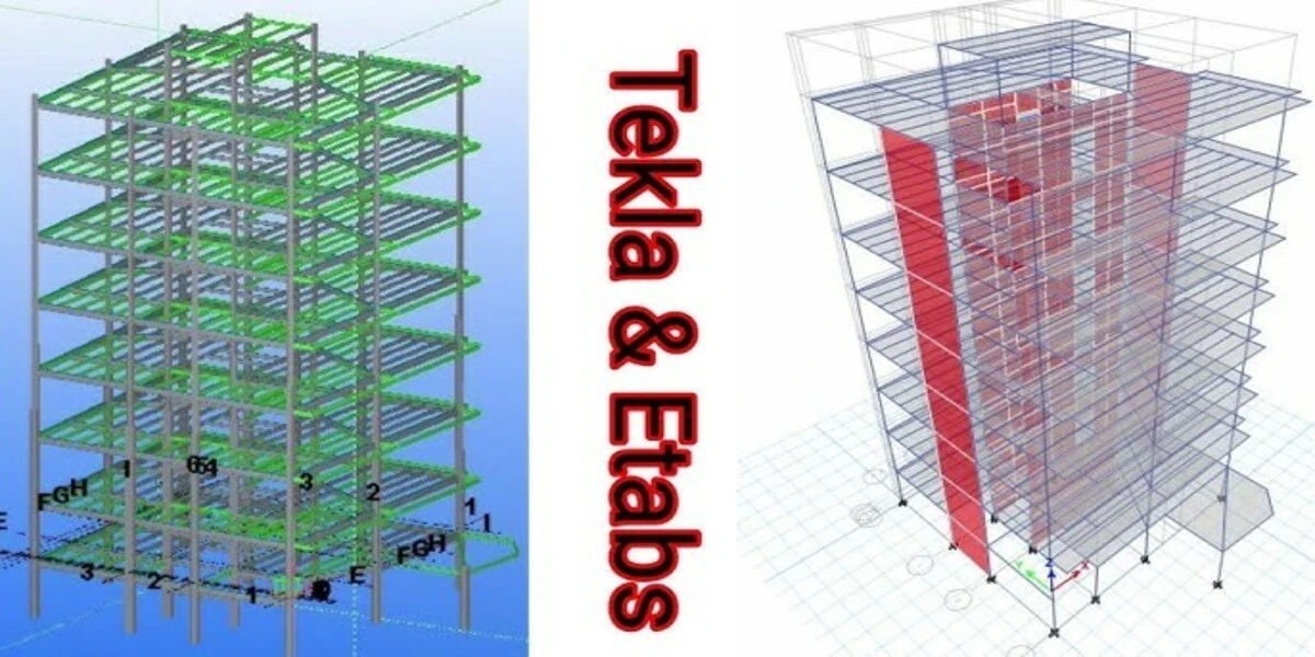
For structural engineering firms operating across the United States, selecting the primary computational engine for lateral analysis is a multi-million-dollar strategic decision.
Designing structures to withstand extreme wind loads along the hurricane-prone Atlantic seaboard or high seismic forces along the Pacific Rim requires strict compliance with building codes such as ASCE 7, the International Building Code (IBC), AISC 360 (steel), and ACI 318 (reinforced concrete).
For decades, Computers and Structures Inc. (CSI) ETABS has reigned as the undisputed industry standard for finite element analysis (FEA) and dynamic lateral design.
However, Trimble’s Tekla Structural Designer (TSD) has drastically disrupted traditional engineering office pipelines.
Tekla Structural Designer challenges the status quo by introducing an integrated physical-analytical hybrid approach that merges global analysis and physical member design into a single, automated database.
This comprehensive technical guide evaluates the core structural engines, load-distribution logic, seismic capability, and BIM synchronisation pipelines of both platforms, helping structural principles and senior engineers select the right tool for their production environment.
Recommended Articles
- Ultimate 2026 Hardware Guide for Revit, Civil 3D, and Tekla Structures: Stop the Viewport Lag
- How To Choose the Best Laptops for Structural Engineers & BIM Managers (2026 Edition)
- Pre-Qualification For Contractors: The First Step to Project Success
- Apply Before It’s Too Late: High-Value Scholarships Closing This Month
- How to Apply for The Knight-Hennessy Scholars Program: The Step-by-Step Guide
The Analytical Node vs. The Physical Asset
The fundamental dividing line between ETABS and Tekla Structural Designer lies in how they represent structural components mathematically.
This affects how fast a model can be built, how errors are debugged, and how data flows to production drawings.
CSI ETABS: The Pure Analytical Matrix
ETABS treats a building strictly as a highly advanced finite element analytical matrix. Columns, beams, and braces are modelled primarily as one-dimensional frame elements (lines), while shear walls and floor slabs are generated as two-dimensional shell or plate elements.
These elements are bound together by explicitly defined node constraints and rigid or semi-rigid diaphragms.
Because it prioritises the mathematical matrix above physical geometry, it gives the engineer total control over structural behaviour.
You can manually adjust the stiffness modification factors of individual shear wall panels to account for concrete cracking (0.35Ecg for beams and 0.70Ecg for uncracked walls per ACI 318), fine-tune the size and density of your finite element mesh, and control localised node spring stiffnesses.
However, ETABS does not natively understand the physical boundaries of these components out of the box.
In ETABS, a beam is a line connecting two points. It doesn’t inherently account for physical flange widths, clear-span clearances, or physical member collisions.
Consequently, once analysis is complete, engineers must often export internal force envelopes to external spreadsheets, specialised design tools, or secondary modules (such as CSI SAFE) to calculate actual rebar spacing, steel baseplate designs, or foundation dimensions.
Tekla Structural Designer: The Physical-Analytical Hybrid
Tekla Structural Designer operates on a physical-first framework. When you place a column or a foundation mat in TSD, you are manipulating an actual physical asset with explicit dimensional boundaries, material weight classifications, and physical spatial constraints.
In the background, TSD automatically generates and maintains a parallel analytical wireframe and finite element mesh.
When you execute an analysis, Tekla Structural Designer runs the mathematical matrix calculations and immediately applies those internal forces to design the actual physical members against US building codes inside the same interface.
Lateral Force Pipelines & Wind Loading Automations (ASCE 7)
Applying multi-directional lateral forces to irregular, non-orthogonal structures is one of the most tedious and error-prone bottlenecks in a structural production environment.
The ETABS Wind Application Method
In ETABS, applying code-compliant wind forces typically requires a two-step process. For standard rectangular high-rises, engineers can utilise the internal ASCE 7 wind load generator, which automatically calculates lateral forces based on basic wind speeds, exposure categories, and gust factors, applying them directly as concentrated horizontal forces at the centre of mass of each floor diaphragm.
However, if the structure features complex geometry—such as stepped roofs, large canopies, open atriums, or non-orthogonal facades—the centre-of-mass approach falls short.
Engineers are forced to manually compute wind pressures for individual windward, leeward, and sidewall zones using external ASCE 7 calculations, and then manually apply those pressures as area loads onto custom shell elements or dummy windward claddings.
The Tekla Structural Designer Wind Wizard Framework
Tekla Structural Designer completely re-engineers this pipeline with its built-in, spatial Wind Wizard optimised for US codes.
By inputting the building’s geographic location, exposure coefficients, and topographic factors, Tekla Structural Designer constructs a comprehensive, 3D wind envelope around the physical structure.
The software executes a process known as wind decomposition. Instead of simply dumping an aggregated force at a floor’s centre of mass, Tekla Structural Designer automatically traces how wind pressure strikes the exterior building skin and decomposes those pressures into linear and area loads distributed directly onto the physical framing members—including perimeter columns, spandrel beams, and roof purlins.
This handles complex, non-rectangular building profiles seamlessly, compressing what used to be days of manual loading calculations into a few minutes of automated processing.
Seismic Analysis & Dynamic Solver Engines
When a structural firm handles projects in high-seismic regions (Seismic Design Categories D through F), the analytical requirements shift from static load-stepping to complex dynamic simulations.
Where ETABS Rules the Structural Engineering Industry
For high-seismic design, performance-based design (PBD), and tall-building lateral validation, CSI ETABS remains the global gold standard.
It houses an incredibly robust mathematical solver engine optimised for:
- Response Spectrum Analysis (RSA): Automated generation of ASCE 7 seismic design response spectra with advanced modal combination techniques (CQC and SRSS).
- Linear and Non-Linear Time History Analysis: Simulating real-world earthquake ground acceleration records using Fast Nonlinear Analysis (FNA) or direct integration methods.
- Material Non-Linearity & Plastic Hinges: Assigning explicit plastic hinges to structural steel frames or fibre-element models to concrete shear walls to analyse post-yield behaviour and energy dissipation during a seismic event.
If you are designing a 40-story reinforced concrete tower in Seattle using a dual system (shear wall core + special moment frames) that requires rigorous non-linear validation to prove structural safety under maximum considered earthquakes, ETABS provides the precise node control, boundary element tracking, and non-linear mathematical stability required to pass peer-review panels.
Tekla Structural Designer’s Seismic Scope: Optimised for the Core Market
Tekla Structural Designer is fully capable of executing code-compliant seismic design using the Equivalent Lateral Force (ELF) procedure and standard Response Spectrum Analysis according to ASCE 7.
It automatically generates seismic load combinations, accounts for accidental eccentricities, evaluates structural irregularities, and calculates critical parameters such as building drift, torsional amplification factors, and stability coefficients.
However, Tekla Structural Designer is explicitly optimised for the high-volume, mainstream commercial market—low-to-medium-rise offices, mixed-use residential podiums, warehouse facilities, and industrial structures.
It does not contain the advanced non-linear time history solvers or plastic hinge mechanics found in ETABS.
If a project crosses into the realm of complex performance-based seismic design or base-isolated high-rises, Tekla Structural Designer is engineered to pass the model to more specialised analytical tools.
Multi-Material Optimisation and Embodied Carbon Tracking
Modern American engineering practices face an evolving double mandate: optimise structural efficiency to lower developer material costs, while auditing and minimising the building’s environmental impact.
TSD’s Automated Optimisation & Carbon Engine
Because Tekla Structural Designer manages the physical definition of structural members, it features exceptional multi-material optimisation workflows within a single interface.
An engineer can seamlessly model a composite steel floor system supported by a reinforced concrete podium deck resting on a mat foundation without switching files or manually copying and pasting reaction forces.
- Autodesign Mode: Tekla Structural Designer can independently iterate through thousands of section sizes. For example, it will scan the entire AISC database to select the shallowest or lightest W-shape steel beam that satisfies both strength safety factors and strict live-load deflection limits.
- Embodied Carbon Calculator: Tekla Structural Designer includes a native carbon-tracking utility. By entering localised carbon factors per unit volume for concrete mixes and steel weights, Tekla Structural Designer calculates the total embodied carbon of the structural frame in real time during the sizing phase. If you change a beam size or alter a concrete grade, you immediately see the impact on your project’s carbon footprint.
ETABS Optimisation and Material Data Handling
ETABS can perform automated steel section selection based on demand-capacity ratios, but its optimisation parameters focus heavily on pure structural behaviour rather than material logistics.
Because it operates within an analytical environment, tracking material takeoffs, calculating concrete rebar tonnage, or conducting carbon accounting usually requires exporting frame forces and geometry into external building information modelling software or custom corporate Excel matrices.
BIM Integration and Multi-Disciplinary Coordination Loops
The efficiency of a structural firm relies heavily on how cleanly its models exchange data with architects, MEP engineers, and steel fabricators.
Tekla’s Open BIM and Revit Integration
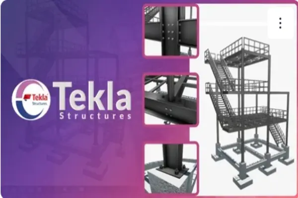
Tekla Structural Designer offers exceptional, bi-directional integration with Autodesk Revit and Tekla Structures. Because TSD stores physical assets rather than just analytical lines, it shares a nearly perfect mapping language with Revit’s structural elements.
When an architect alters grid lines, adds door openings through concrete shear walls, or adjusts floor-to-floor heights in Revit, those modifications sync cleanly into Tekla Structural Designer via a dedicated integration link.
Tekla Structural Designer automatically updates the physical members and auto-recreates the underlying analytical wireframe mesh.
The engineer can immediately re-run the calculation passes without spending hours manually rebuilding or re-meshing the model.
ETABS and the Revit Coordination Loop

CSI provides tools like the CSIxRevit plug-in to facilitate data transfer between ETABS and Autodesk Revit, but the translation frequently requires manual intervention.
Because ETABS interprets a building through analytical node locations rather than physical assets, importing complex or organic Revit geometry often results in misaligned nodes, disconnected frame elements, or overlapping shell meshes.
Engineers frequently have to spend significant project hours manually cleaning up the analytical model inside ETABS before running calculations.
Technical Comparison Matrix: Tekla Structural Designer vs. ETABS
| Evaluation Parameter | CSI ETABS | Tekla Structural Designer |
| Primary Software Domain | Advanced Finite Element Analysis (FEA) | Integrated Physical Modeling, Analysis & Design |
| US Building Code Focus | ASCE 7, IBC, AISC 360, ACI 318, AWS | ASCE 7, IBC, AISC 360, ACI 318 |
| Advanced Seismic Tracking | Non-Linear Time History, PBD, Plastic Hinges | Equivalent Lateral Force, Response Spectrum |
| Wind Loading Application | Manual or basic center-of-mass diaphragm loads | Automated 3D Wind Wizard with decomposition |
| Material Sizing Workflows | Sizes sections based on frame force demands | Automated weight optimization from member catalogs |
| Embodied Carbon Auditing | Requires external calculation loops | Built-in, real-time embodied carbon tracking |
| Revit Synchronization | Requires analytical node cleanup via CSIxRevit | Direct, clean bi-directional physical model sync |
Frequently Asked Questions (FAQs)
1. Can I open a Tekla Structural Designer model directly inside ETABS?
No, there is no direct, native file format compatibility between the two applications. To share structural models between them, you must export the model geometry using a universal open format such as IFC (Industry Foundation Classes) or a CIS/2 data exchange file. While this transfers the physical frame configuration, underlying analysis parameters, load combinations, and specific design settings must be configured fresh in the receiving application.
2. Is ETABS harder for junior structural engineers to learn than Tekla Structural Designer?
Yes, ETABS typically has a steeper learning curve because it requires a strong understanding of finite element analysis (FEA) mechanics. A user must understand how to manually manage mesh densities, apply diaphragm constraints, and resolve node instability errors. Tekla Structural Designer is generally considered more intuitive for incoming engineers because its interface models real-world components (like actual columns and beams) and automates the analytical mesh generation in the background.
3. Why does ETABS remain dominant in high-seismic regions like California?
ETABS dominates West Coast and seismic-prone engineering markets because local building departments and independent structural peer-review panels demand highly detailed verification of post-yield behaviour. ETABS’s decades-long history of reliable solvers for non-linear time-history analysis, performance-based design (PBD), and complex shear-wall boundary-element calculations makes it the most trusted and legally defensible engine for tall-building verification in high-risk zones.
4. How do these programs handle foundation design?
Tekla Structural Designer features built-in foundation design modules directly inside the primary user interface. It can analyse and design isolated pad footings, strip footings, pile caps, and massive mat foundations against ACI 318 codes within the same model file. ETABS handles global foundation analysis but relies on its sister application, CSI SAFE, to execute detailed concrete rebar layouts and punching shear checks for foundation slabs.
5. Can both programs run natively on macOS hardware?
No, both CSI ETABS and Tekla Structural Designer are strictly Windows-native applications. They cannot run natively on Apple Silicon (M1 through M4 series) or Intel-based Macs. To run either program on Apple hardware, engineering firms must utilise Windows virtualisation environments like Parallels or host the software on cloud-based Windows workstations, which can introduce performance overhead during heavy analysis runs.
Conclusion: Matching the Software to Your Firm’s Project Profile
The technical debate between Tekla Structural Designer and ETABS is not about finding an absolute winner—it is about choosing the tool that matches your firm’s specific project profile, production speed, and structural demands.
- Standardise on CSI ETABS if: Your practice focuses on high-rise structures, complex lateral framing systems, performance-based seismic design, or retrofitting historic buildings in major high-seismic zones. If your daily production relies on total control over finite element meshes, custom material hinges, and advanced non-linear solvers, ETABS remains the premier choice for structural analysis.
- Standardise on Tekla Structural Designer if: Your project portfolio consists primarily of low-to-medium-rise commercial office spaces, residential podiums, retail centres, industrial warehouses, or institutional facilities. If you want to accelerate delivery times by combining analysis and physical member design into a single step, automate complex ASCE 7 wind-load mapping, and maintain a seamless, error-free integration with Autodesk Revit, Tekla Structural Designer offers a highly efficient alternative to traditional engineering workflows.
Thats All.
Let’s Talk.

