
A Combined footing is a single footing supporting two or more columns. Moreover, a Combined footing is commonly used when two or more columns are spaced too closely, where two isolated footings would be unsatisfactory.
Recommended Articles
- Design of Staircase: The Complete Guide to Civil Engineers
- Open University of Tanzania: You Should Apply Right Now
- What Does a Project Manager Do in the Construction Site?
- Water Treatment: The Complete Guide to All Civil Engineers
- Bill Of Quantity (BOQ): Everything You Need To Know
- What do an Engineer do? | All You Need To Know
- How To Be a Professional Engineer With Examples In 2026
- How to Simply Estimate Footings Foundation Reinforcements
Table of Contents
How To Design a Combined Footing
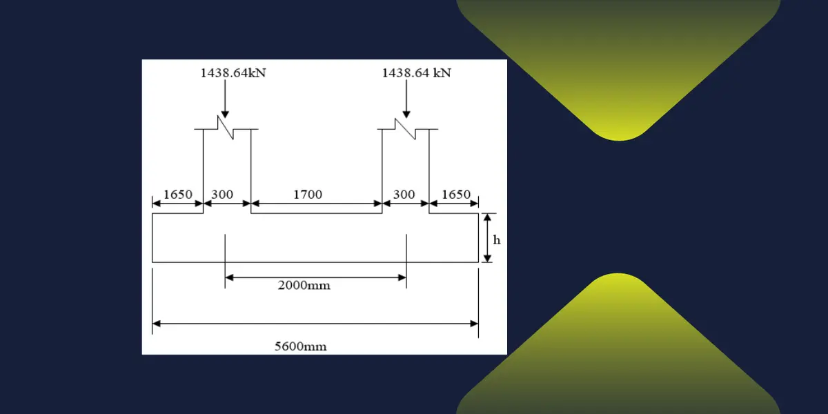
Before starting to design, let’s assume the following data:
- Ultimate designed axial load = 2014.1KN
- Serviceability axial load = 1438.64KN
- Serviceability moment = 16.81kNm
- Fcu = 30N/mm2
- Fy = 460N/mm2
- Steel reinforcement = 20mm
- Soil bearing capacity = 200kN/m2
- Size of column = 300mmx300mm
For the serviceability limit state
- Assumed footing weight = 250KN
- Therefore, Total serviceability load = 1438.64 + 250 + 1438.64 = 3127.28KN
Base area allowed = total load/safe bearing pressure
- Base area allowed = 3127.28KN/200 kN/m2 = 15.6m2
- Assume rectangular base = 2.8B
- Fix 2.8 one side, then = 2.8B = 15.6
- B = 5.6 m


For the ultimate limit state

Assume a 625mm thick footing, with the footing constructed on a blinding layer of concrete, and the minimum cover is taken as 50mm.
- Therefore, self-weight of footing = Area * h * γconcrete
- 2.8*5.6 * 0.625 * 24 = 235.2KN < assumed weight, 250KN
- The Self-weight of the footing should be equal to or less than the assumed weight of the footing
From above:
- Effective depth, d = h – cover – θ/2
- Therefore, Effective depth, d = 625 – 50 – 10
- Effective depth, d = 565mm
Shear stress, vc = N/column perimeter * d
Therefore:
- Shear stress, vc = 2014.1*103/1200*565
- Shear stress, vc = 2.97 N/mm2

Bending Reinforcements

Longitudinal bending

- Provide: Y25 – at 125mm centres
- As prov = 3927mm2, top

- Provide: Y16 – at 150mm centres
- As prov = 1340mm2
M = earth pressure * pad size * (projection/2)2

From above:
- Provide: Y25 – at 125mm centres
- As prov = 3927mm2
Conclusion
Today, we have designed a combined column. I hope you have found something. Use the comments form for advice, comments, or anything you think we can share.

")