
A staircase is a set of stairs that connects the different floors of a building. In structural design, the staircase is designed without a string. The flight is intended to act as a slab spanning between the trimmers.
In this case, the flight span is the horizontal distance between the two centres of the trimmers. The effective span of the slab is designed on the same basis as a floor slab.
Recommended Articles
- Structural Elements: Everything You Need To Know About Beams
- Substructure and Superstructure: The Complete Guide
- Structural Engineer | All You Need To Know
- What Does a Project Manager Do in the Construction Site?
- Water Treatment: The Complete Guide to All Civil Engineers
- Skills For Engineers For The Job Market: The Quick guide
Table of Contents
Design of Staircase
Today, let’s take a brief look at how to design a staircase. We will look for the flight and landing. Keep following this post until the end.
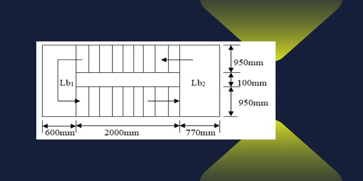
In this example, we will use the figure below. Don’t worry about the measurements in this drawing because they are only design measurements.
Please note: This design is based on BS 6399 Part 1:1984 Code of Practice of Dead Load and Imposed Load, BS 8110 Part 1:1985 Code of Practice for design and Construction, and BS 8110 Part 1: 1997 Code of Practice for design and construction.

For comfort, the dimensions should be within the following rules
- 2R + G = 570mm – 630mm
- R ≤ 190 mm
- G ≥ 225mm
- nR ≤ 16 per flight
- α ≤ 38˚
Consider the following dimensions:
- Riser, R= 150mm
- Going, G= 250mm
- Landing (Lb2) = 770mm
- Landing (Lb1) = 660mm
- Waist thickness = 150mm
Effective span, Le
- Le = La +0.5 (Lb1+ Lb2)
- Le = 2000 +0.5 (600+ 770)
- Le = 2685mm
Factor:

Factor = (1/cos 31) = 1.167
Consider a 1m width of the stairs
Loading
Dead load, Flight
- Waist = 0.15 * 24* 1.167 =4.2 kN/m2
- Steps = 0.15 * 0.5 * 24 = 1.8 kN/m2
- Finishes = 1.8 kN/m2
- Total dead load, Gk = 7.8 kN/m2
- Designed dead load = 1.4 *7.8 = 10.92 kN/m
Dead load, Landing, Lb1
- Self weight = 0.15 * 24 = 3.6 kN/m2
- Finishes =1.8 kN/m2
- Total designed load = 1.4 *5.4 =7.56 kN/m
Dead load, Landing, Lb2
- Total designed load = 1.4 *5.4 =7.56 kN/m
- Imposed load = 3 kN/m2
- Designed imposed load = 1.6 * 3 = 4.8 kN/m
Determination of reactions, dead load

- RA = 13.69KN
- RB = 13.44KN
- Mmax = 9.74 kNm at 1.3 m from left.

Determination of reactions, imposed load

- RA = RB = 6.35 KN
- Mmax = 4.37 kNm
- Moment at 1.3m = 4.2 kNm

By superimposing the dead and imposed loads moments
- Both moments at 1.3m from the left
- Mmax designed moment = 9.74 kNm + 4.2 kNm
- Mmax designed moment= 13.94 kNm
Design of stair flight reinforcements
Diameter of steel = 10mm (assumed)
- Mmax designed moment= 13.94 kNm
- Cover = 25mm
- fcu = 25N/mm2
- fy = 460N/mm2
- Condition of exposure MILD
- Nominal cover = 25mm
- Fire resistance = 1.5hrs
- Assume continuity
Effective depth, d


From the BS 8110-1-1985 Grouped bar Area table:
- Provide: Y10 – 200 mm C/C
- Asy provided: 393 mm2/M
Distribution bars

- Provide: Y10 – 300 mm C/C
- Asy provided: 262 mm2/M
Checks
Spacing provided = 200 mm <3d OR 750
= 200 mm < 360mm OR 750mm……OK
2. Deflection


26 mm < 32 mm ………………………………..Deflection OK
Design of Landing
Loading
Dead load
- Self weight = 0.15 * 24 = 3.6 kN/m2
- Finishes and services = 1.8 kN/m2
- Total dead load, Gk = 5.4 kN/m2
- Imposed load, Qk = 3 kN/m2
- Designed load, n = 1.4Gk + 1.6 Qk
- n = 1.4*5.4 + 1.6 *3 = 12.36 kN/m2
Designed load per metre run of landing
- n = 12.36 kN/m2 * Landing + reaction
- n = 12.36 *0.77 + 13.69= 23.21 kN/m
Loading system

RA = RB = 23.21 KN
Mmax = 12 kNm

Design of landing: Designed moment = 12 kNm

- Provide: Y10 – 250 mm C/C
- Asy provided: 314 mm2/M
Secondary bars
- As min = 195 mm2/M
- Provide: Y10 – 300 mm C/C
- Asy provided: 262 mm2/M
Conclusion on Staircase
Today, we created a staircase design. Here is a very brief one. I hope you have found something to start your engineering journey. Use the comments form for advice, comments, or anything you think we can share.
Join the conversation by replying on Bluesky.
That’s all.

")